
Telescopic infrared temperature measuring device

An infrared temperature measurement and telescopic technology, which is applied in the direction of measuring devices, optical radiation measurement, radiation pyrometry, etc., can solve the problems of difficult to obtain the temperature distribution of equipment, poor flight conditions, and high degree of danger, so as to save observation time , Expand the measurement range, increase the effect of contact area

Pending Publication Date: 2021-06-18
STATE GRID ZHEJIANG ELECTRIC POWER CO LTD JINHUA POWER SUPPLY CO
View PDF5 Cites 0 Cited by
  • Summary
  • Abstract
  • Description
  • Claims
  • Application Information

AI Technical Summary

Problems solved by technology

There are more or less certain problems when these devices are applied to the infrared temperature measurement of the power distribution system. Taking the handheld infrared thermometer as an example, the control range that can be detected is relatively small. When the required detection equipment When the location is out of the control range of the operation and maintenance personnel or is blocked by other objects, it is difficult to obtain the temperature distribution of the equipment
Taking the drone equipped with an infrared temperature measurement platform as an example, when measuring the temperature of key equipment in the transmission corridor, it can cover a large monitoring range, but when measuring the temperature of related equipment in the substation, due to the equipment in the substation The distribution is relatively dense, and the location is mostly low. For UAVs, the flying conditions are extremely harsh and the degree of danger is relatively high. Therefore, it is difficult for UAVs to carry infrared temperature measurement platforms in substations.

Method used


Image

  • Telescopic infrared temperature measuring device
  • Telescopic infrared temperature measuring device
  • Telescopic infrared temperature measuring device

Examples


Embodiment 1

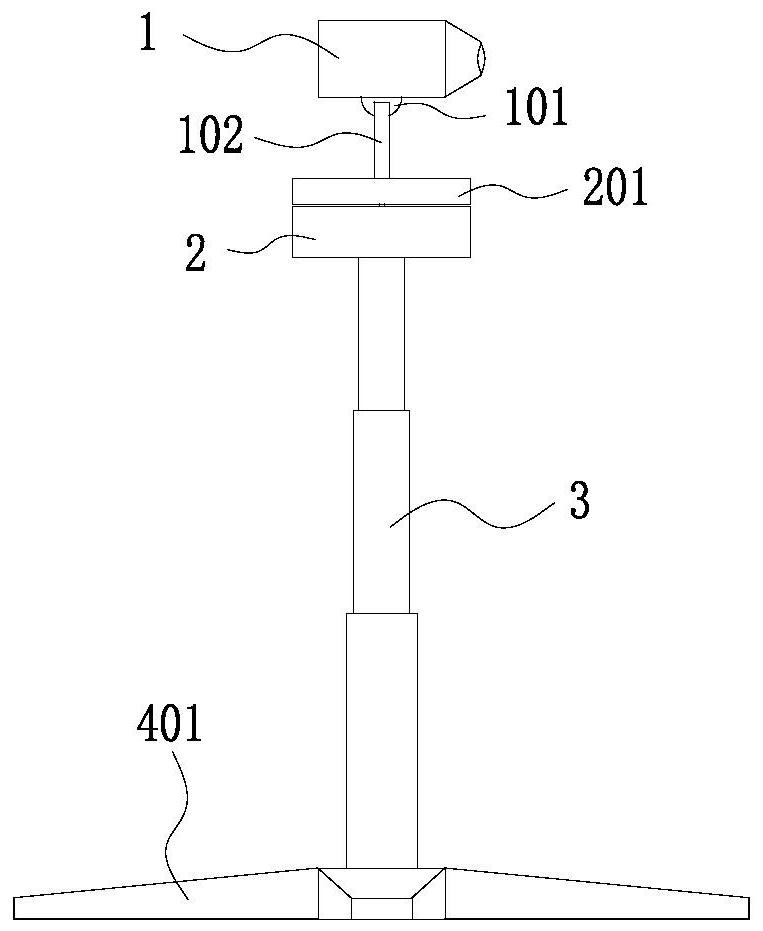
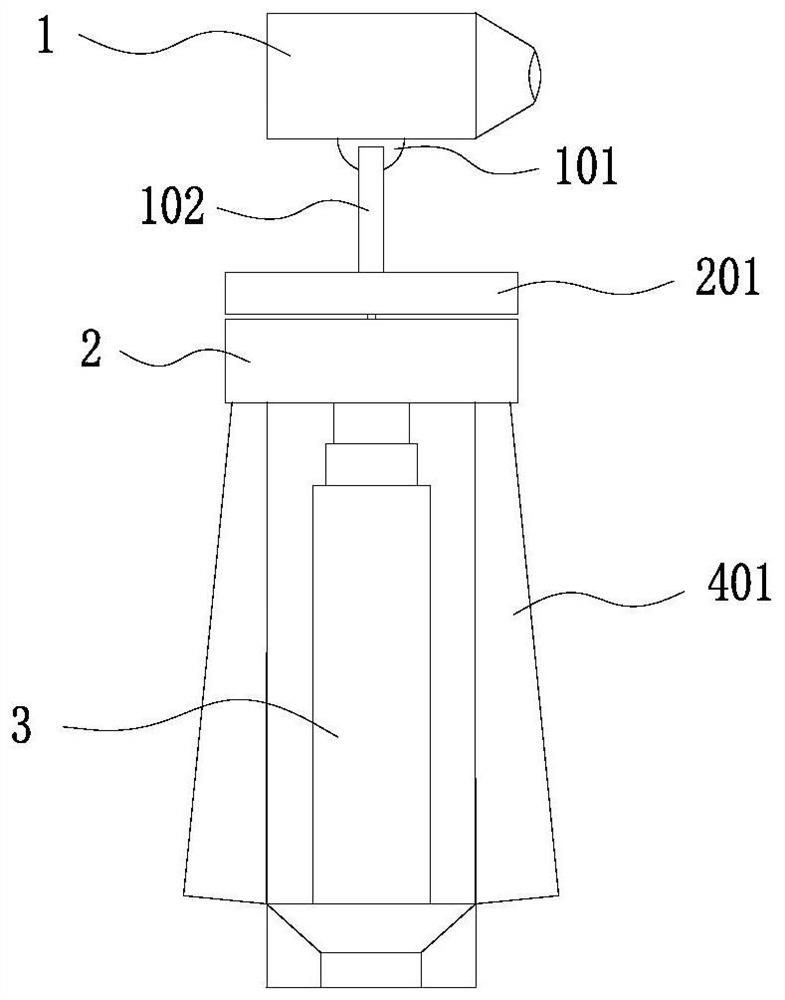
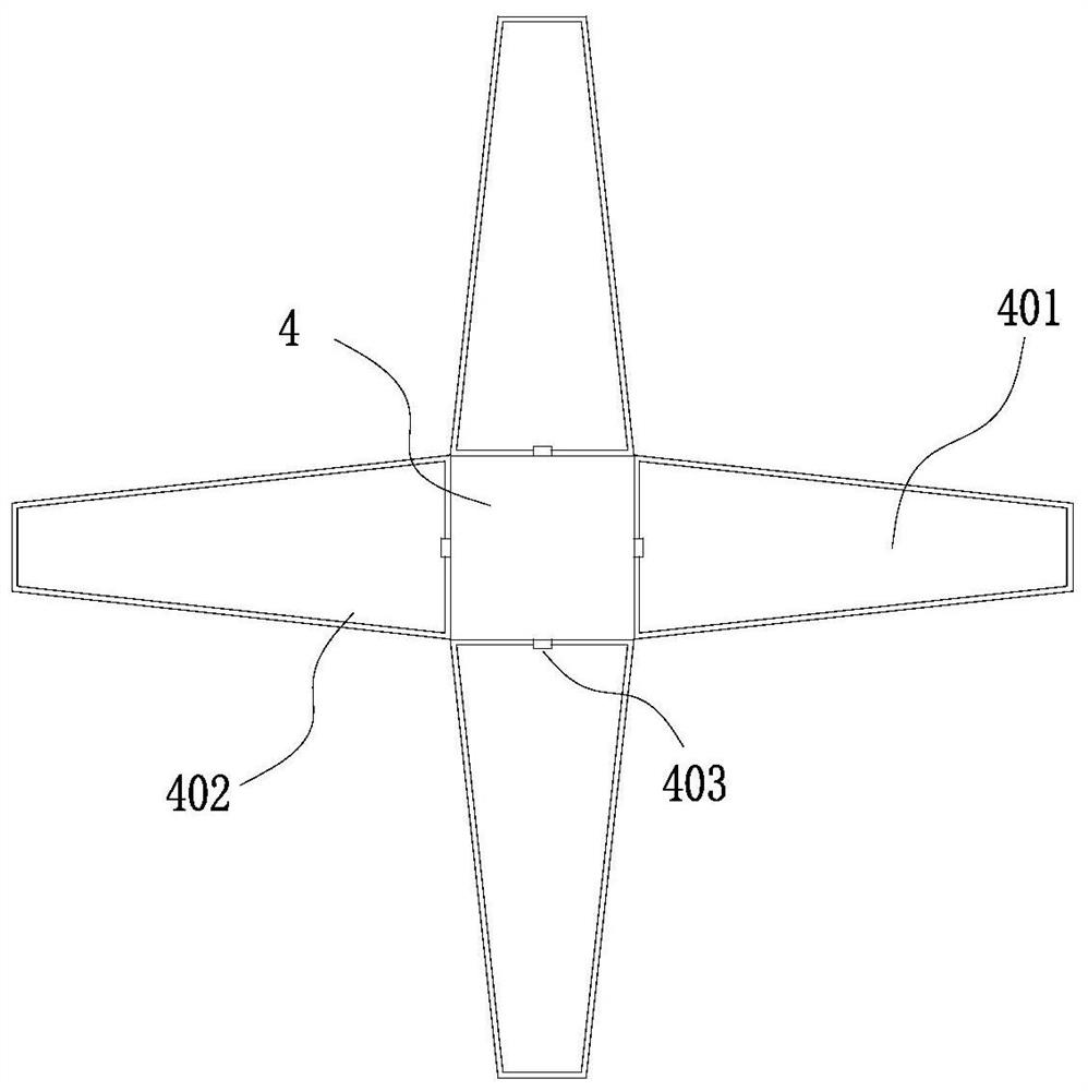
[0030] Such as Figure 1 to Figure 4 As shown, this embodiment shows a retractable infrared temperature measuring device, which is characterized in that it includes a base 4, a telescopic rod 3, an infrared instrument 1 and an intelligent device, and a plurality of supports 401 are provided on the side of the base 4 , the support members 401 are arranged at intervals around the base 4, the support members 401 are rotationally connected with the base 4, and the base 4 is provided with a fixing member. When the support members 401 are rotated to be flush with the base 4 , the support member 401 and the base 4 are fixed by a fixing member, one end of the telescopic rod 3 is installed on the base 4, and the other end is provided with a connecting plate 2, and the lower side of the connecting plate 2 is provided with a The groove 202 at the end of 401, the upper side of the connecting disk 2 is provided with a rotating disk 201, the connecting disk 2 is provided with a controller, ...


PUM


Abstract

The invention discloses a telescopic infrared temperature measuring device which comprises a base, a telescopic rod, an infrared instrument and intelligent equipment, wherein a plurality of supporting pieces are arranged on the side edge of the base, the supporting pieces are rotationally connected with the base, fixing pieces are arranged on the base, the supporting pieces are fixed to the base through the fixing pieces, one end of the telescopic rod is installed on the base, the other end of the telescopic rod is provided with a connecting disc, the lower side of the connecting disc is provided with grooves used for containing the ends of the supporting pieces, the upper side of the connecting disc is provided with a rotating disc, a controller is arranged in the connecting disc and controls the rotating disc to rotate, the rotating disc is provided with a supporting column, the infrared instrument is rotationally connected with the end of the supporting column, and the intelligent equipment is connected with the infrared instrument through a wireless transmission technology. The infrared temperature measuring device can avoid sheltering objects, and the temperature measuring range is expanded.

Description

【Technical field】 [0001] The invention relates to a retractable infrared temperature measuring device, which belongs to the technical field of infrared temperature measuring devices. 【Background technique】 [0002] Infrared temperature measurement technology is one of the practical applications of applying infrared theory to the temperature acquisition of power equipment. When the power equipment is running, it will be accompanied by the heating of the surface of the equipment, and the development and formation of most faults are related to heat. close relationship. Therefore, the temperature distribution of the equipment surface obtained by infrared temperature measurement technology can be used as one of the evaluation indicators of the equipment's operating status, and the operation and maintenance personnel can evaluate the equipment's operating status through the heating of the object surface, which is a comprehensive engineering application. technology. [0003] At p...

Claims


Application Information

Patent Timeline
IPC IPC(8): G01J5/00G01J5/02
CPCG01J5/0096G01J5/0205G01J2005/0077
Inventor 赵新语吴胥阳范旭明陈文通周彪王颖剑黄晓峰张健聪周旺郎诚陆丰李立新
Owner STATE GRID ZHEJIANG ELECTRIC POWER CO LTD JINHUA POWER SUPPLY CO
Learn More