Supercharge Your Innovation With Domain-Expert AI Agents!

Strain gauge, and preparation method and installation method thereof

A technology of strain gauges and conductive layers, applied in the field of sensors, can solve problems such as low assembly efficiency, and achieve the effect of reducing production costs and improving assembly efficiency

Pending Publication Date: 2021-06-18
BEIJING TAIFANG TECH CO LTD
View PDF8 Cites 1 Cited by
  • Summary
  • Abstract
  • Description
  • Claims
  • Application Information

AI Technical Summary

Problems solved by technology

[0004] The embodiment of the present invention provides a strain gauge and its preparation method and installation method, which are used to solve the problem of low assembly efficiency of conventional strain gauges pasted on the metal surface by means of glue

Method used


Image

  • Strain gauge, and preparation method and installation method thereof
  • Strain gauge, and preparation method and installation method thereof
  • Strain gauge, and preparation method and installation method thereof

Examples


preparation example Construction

[0059] In one embodiment, an embodiment of the present invention provides a method for preparing a strain gauge, including:

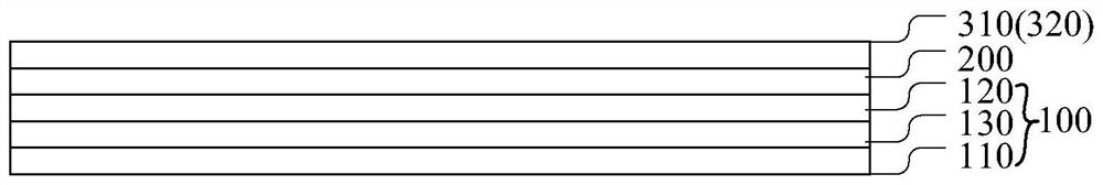
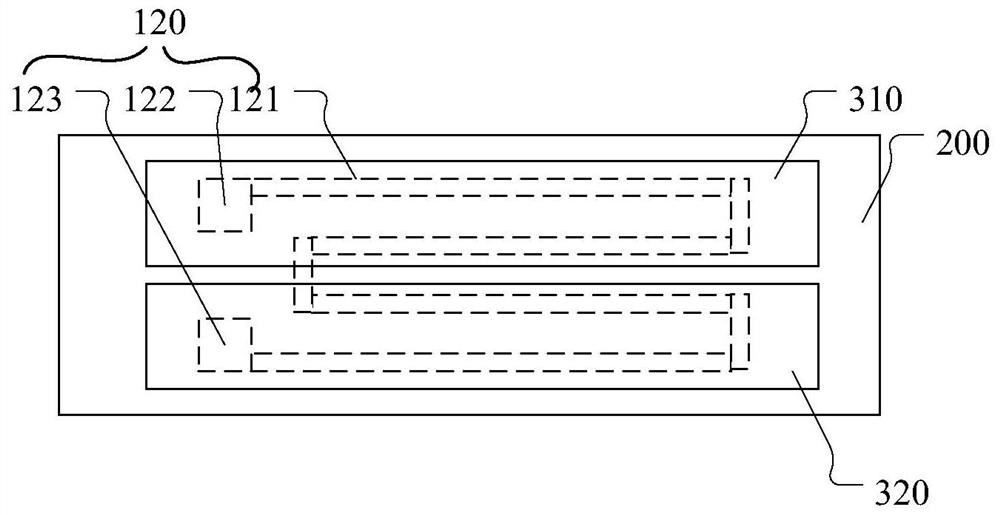
[0060] A first protective layer is formed on the strain gauge body, and a first opening corresponding to the position of the first lead end and a second opening corresponding to the position of the second lead end are formed on the first protective layer, wherein the strain gauge body includes A sensitive gate layer, the sensitive gate layer includes at least one sensitive gate, and the sensitive gate includes a first lead end and a second lead end;

[0061] A first conductive layer and a second conductive layer are formed on the side of the first protective layer away from the strain gauge body, the first conductive layer is electrically connected to the first lead end at the first window opening position, and the second conductive layer is at the second window opening position It is electrically connected with the second lead terminal.


PUM


Abstract

The embodiment of the invention discloses a strain gauge, and relates to the technical field of sensors. The strain gauge comprises: a strain gauge body, wherein the strain gauge body comprises a sensitive grid layer, the sensitive grid layer comprises at least one sensitive grid, and the sensitive grid comprises a first lead end and a second lead end; a first protection layer arranged on the strain gauge body, wherein the first protection layer is provided with a first window corresponding to the position of the first lead end and a second window corresponding to the position of the second lead end; and a first conducting layer and a second conducting layer which are arranged on the side, away from the strain gauge body, of the first protection layer in a spaced mode, wherein the first conducting layer is electrically connected with the first lead end at the first windowing position, and the second conducting layer is electrically connected with the second lead end at the second windowing position. According to the embodiment of the invention, the first conducting layer electrically connected with the first lead end and the second conducting layer electrically connected with the second lead end are arranged on the first protection layer at intervals, so that the strain gauge can be directly welded on the metal surface, and the assembly efficiency of the strain gauge on the metal surface is improved.

Description

technical field [0001] The invention relates to the technical field of sensors, and more specifically, to a strain gauge, a preparation method and an installation method thereof. Background technique [0002] Strain gauges are components used to measure strain, which are composed of sensitive grids and the like. The working principle of the resistance strain gauge is based on the strain effect, that is, when the conductor or semiconductor material is mechanically deformed under the action of an external force, its resistance value changes accordingly. This phenomenon is called "strain effect". [0003] At present, conventional strain gauges are generally pasted on metal surfaces by means of glue. This assembly method is inefficient and difficult to apply in large quantities in the current consumer electronics field. Contents of the invention [0004] Embodiments of the present invention provide a strain gauge and its preparation method and installation method, which are u...

Claims


Application Information

Patent Timeline
Patent Type & Authority Applications(China)
IPC IPC(8): G01L1/22G01L9/04
CPCG01L1/2243G01L1/2262G01L1/2287G01L9/04
Inventor 不公告发明人
Owner BEIJING TAIFANG TECH CO LTD
Features
  • R&D
  • Intellectual Property
  • Life Sciences
  • Materials
  • Tech Scout
  • Unparalleled Data Quality
  • Higher Quality Content
  • 60% Fewer Hallucinations
Learn More