Polarizing material, polarizer and display panel

A display panel and polarizer technology, which is applied in the direction of optics, optical elements, polarizing elements, etc., can solve the problems of poor solubility, poor polarization characteristics, insufficient orientation degree, etc., achieve maximum solubility, maximum polarization degree, and improve light extraction efficiency Effect

Inactive Publication Date: 2021-06-18
WUHAN CHINA STAR OPTOELECTRONICS TECH CO LTD
View PDF5 Cites 1 Cited by
  • Summary
  • Abstract
  • Description
  • Claims
  • Application Information

AI Technical Summary

Problems solved by technology

[0006] The object of the present invention is to provide a polarizing material, a polarizer, and a display panel to solve the technical problems of poor solubility, insufficient orientation degree, and poor polarizing characteristics of black dichroic dyes used in existing polarizers

Method used


Image

  • Polarizing material, polarizer and display panel
  • Polarizing material, polarizer and display panel
  • Polarizing material, polarizer and display panel

Examples


Embodiment 1

[0037] This embodiment provides a polarizing material, comprising: reactive liquid crystal, 80-98%; monochromatic dichroic dye, 1-10%; photoinitiator, 0.1-2%; polymerization inhibitor, 0.05% by mass percentage -0.2%; surfactants, 0.05%-5%; and photoresist additives, 0.1-20%.

[0038] Specifically, in terms of structure, the reactive liquid crystals may include acrylic reactive liquid crystals and alkylene oxide reactive liquid crystals; in terms of liquid crystal phases, the reactive liquid crystals may include nematic reactive liquid crystals, near Crystal phase reactive liquid crystal.

[0039] The monochromatic dichroic dyes include cyan dyes, magenta dyes, yellow dyes and other dyes. When the monochromatic dichroic dye is a cyan dye, it is used to absorb red light. When the monochromatic dichroic dye is a magenta dye, it is used to absorb green light. When the monochromatic dichroic dye is a yellow dye, it is used to absorb blue light.

[0040] The photoinitiator is a ...

Embodiment 2

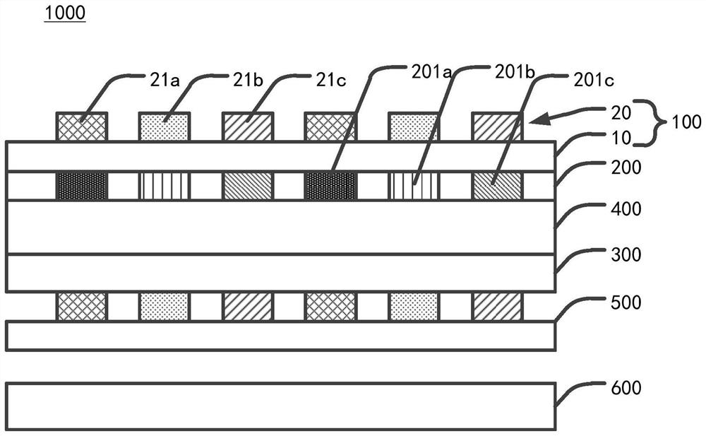
[0076] This embodiment provides a polarizing material, a polarizer and a display panel, which include most of the technical solutions of Embodiment 1, the difference being that the polarizing layer is disposed between the liquid crystal layer and the color filter substrate.

[0077] Such as Figure 5 as shown, Figure 5 It is a schematic structural diagram of the display panel described in Embodiment 2 of the present application.

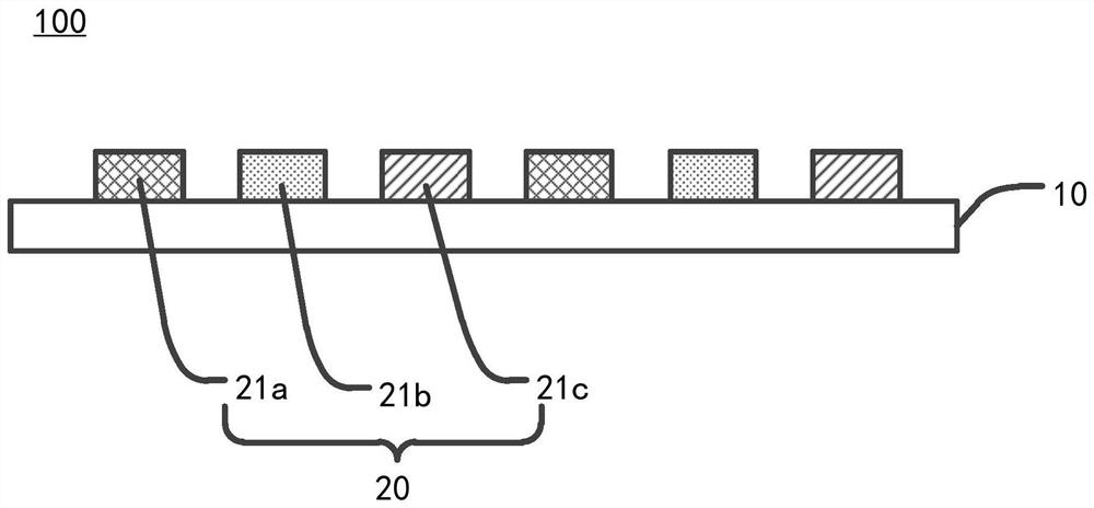
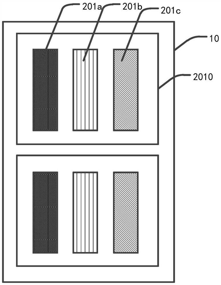
[0078] This embodiment provides a display panel 2000 , the polarizing layer 100 is disposed between the liquid crystal layer 400 and the color filter substrate 200 .

[0079] The color filter substrate 200 includes a red color-resist unit 201a, a green color-resist unit 201b, and a blue color-resist unit 201c. In the polarizing layer 20, the polarizing unit 21 includes a cyan polarizing unit 21a, a magenta polarizing unit 21b, Yellow polarizing unit 21c. Wherein, the cyan polarizing unit 21a corresponds to the red color resist unit 201a, and is u...


PUM


Abstract

The invention discloses a polarizing material, a polarizer and a display panel, and the polarizing material comprises the following components in percentage by mass: 80-98% of reactive liquid crystal; 1-10% of a monochromatic dichroic dye; 0.1-2% of a photoinitiator; 0.05-0.2 percent of a polymerization inhibitor; 0.05%-5% of a surfactant; and 0.1-20% of a photoresist additive. The polarizer is provided with polarizing units with different colors, and each polarizing unit is provided with polarizing materials with different colors. When the polarizer is applied to the display panel, the polarizer is arranged on one of the upper side and the lower side of the color film substrate so that the color system of each polarizing unit is matched with the color system of the color resistance unit, the solubility, the compatibility and the polarization degree of dichroic dye molecules in the polarizer are maximized, emergent light of the red color resistance unit, the green color resistance unit and the blue color resistance unit can be independently regulated and controlled, the polarization characteristic of the polarizer is improved, and therefore the light emitting efficiency of the display panel can be improved.

Description

technical field [0001] The present application relates to the field of display technology, in particular to a polarizing material, a polarizer, and a display panel. Background technique [0002] Today, with the development of display technology, people's demand for display is gradually increasing, display technology is also changing day by day, and display forms are also developing towards diversification. [0003] In order to improve display quality and meet different display requirements, a new type of display technology is developing rapidly, such as Quantum Dot color filter (QDCF) display with high display color gamut, flexible display, ultra-thin display, etc. Polarizers are indispensable and important film materials for this type of display technology, but traditional PVA iodine-based polarizers cannot be built-in (In-cell) or patterned (pattern) due to their thicker film layers and poor flexibility. Therefore, the requirements cannot be met in this type of new displa...

Claims


Application Information

Patent Timeline
Patent Type & Authority Applications(China)
IPC IPC(8): G02B5/30G02F1/1335
CPCG02B5/3016G02F1/133514G02F1/133528
Inventor 何瑞程薇
Owner WUHAN CHINA STAR OPTOELECTRONICS TECH CO LTD
Why Eureka
Try Eureka