Method for describing, evaluating and improving optical polarization properties of a microlithographic projection exposure apparatus

a microlithographic and exposure apparatus technology, applied in the direction of optical radiation measurement, photomechanical apparatus, instruments, etc., can solve the problem that the diffraction order cannot be fully interfering, and achieve the effect of improving quality function, reducing deviations of optical polarization properties, and improving quality function

Active Publication Date: 2010-06-01
CARL ZEISS SMT GMBH
View PDF8 Cites 7 Cited by
  • Summary
  • Abstract
  • Description
  • Claims
  • Application Information

AI Technical Summary

Benefits of technology

[0037]compiling a modified design so that the quality function is improved.
[0038]Various measures may be employed when modifying the design for the optical system in order to improve the quality function. For example, it is possible to rotate birefringent optical elements about the optical axis. It is also feasible to use specially optimized polarization-correcting optical elements, which reduce the deviations of the optical polarization properties from the specifications. Such an element may, for example, be a reflection or antireflection coating which might already be present, the optical polarization effect of which is suitably tuned. A birefringent optical element which has thickness variations produced by local reprocessing may also be a suitable polarization-correcting optical element in this context.

Problems solved by technology

This is related to the fact that the reticle diffracts the transmitted projection light into different diffraction orders, which interfere in the image plane and thereby produce the image of the reticle.
In the case of projection light polarized parallel to the incidence plane (p-polarization), however, different diffraction orders can no longer interfere fully since the diffraction orders have different polarization directions.

Method used


Image

  • Method for describing, evaluating and improving optical polarization properties of a microlithographic projection exposure apparatus
  • Method for describing, evaluating and improving optical polarization properties of a microlithographic projection exposure apparatus
  • Method for describing, evaluating and improving optical polarization properties of a microlithographic projection exposure apparatus

Examples


Embodiment Construction

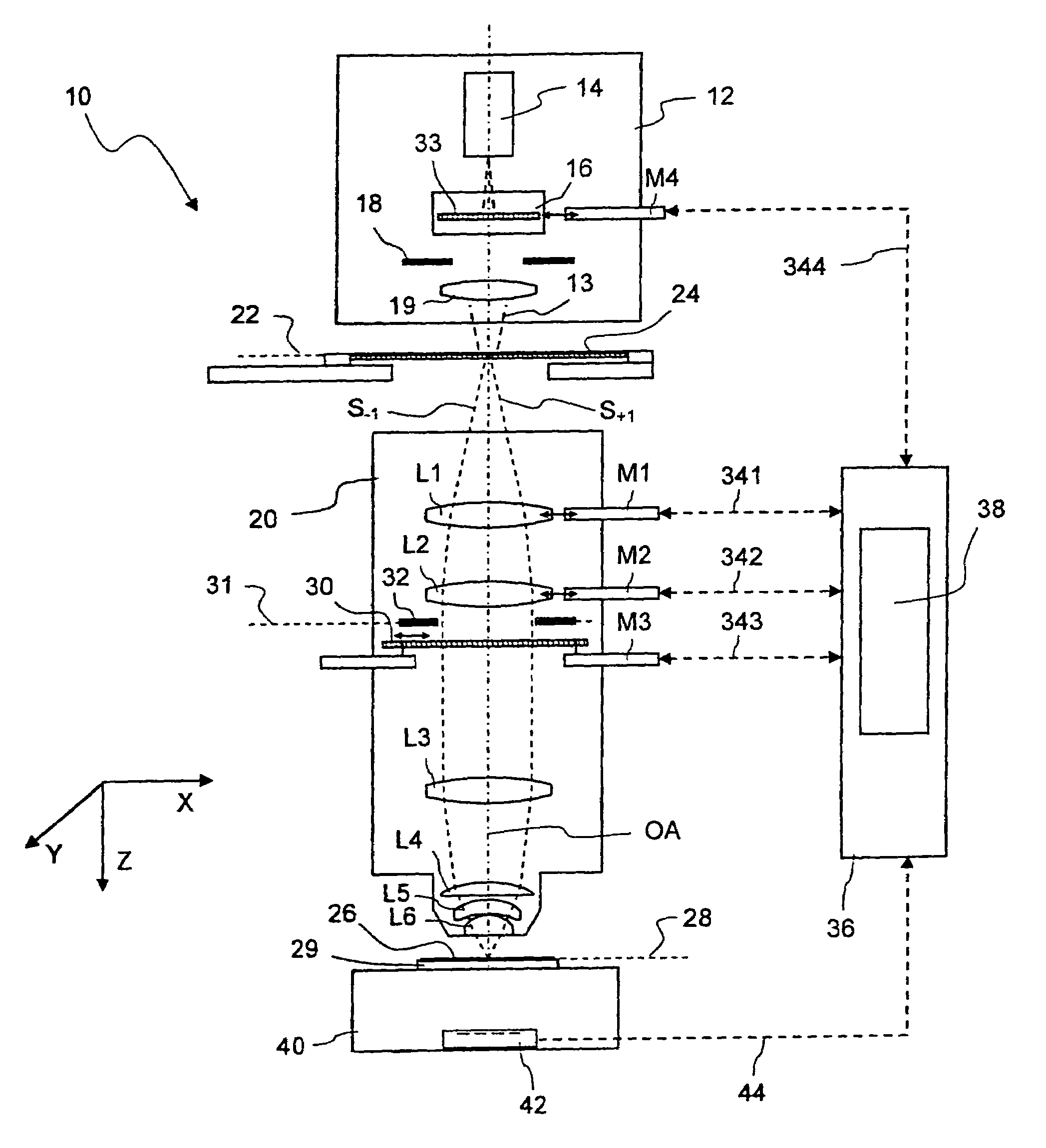
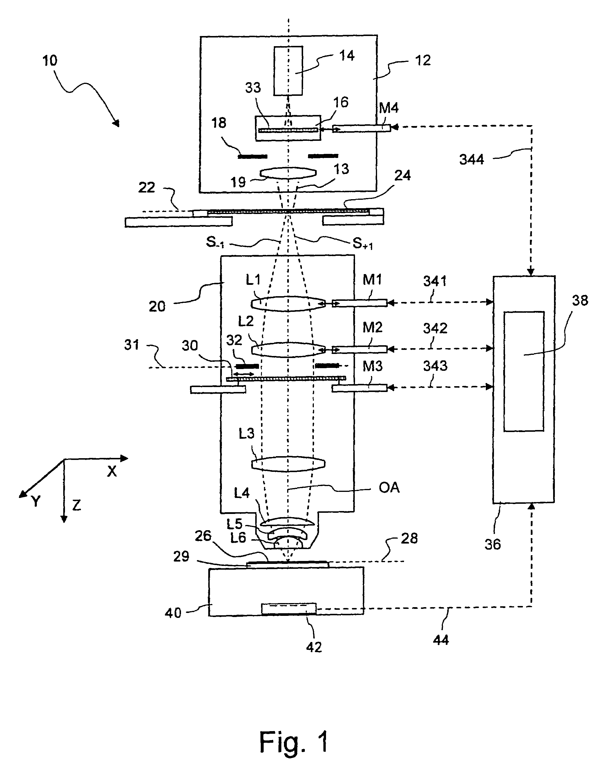
[0060]FIG. 1 shows a meridian section through a microlithographic projection exposure apparatus, denoted overall by 10, in a highly schematized representation which is not true to scale. The projection exposure apparatus 10 has an illumination system 12 for producing projection light 13, which comprises a light source 14, illumination optics indicated by 16 and a diaphragm 18. The illumination optics 16 make it possible to set up different illumination angle distributions. To this end, for example, the illumination device may contain interchangeable diffractive optical elements or microlens arrays. Since such illumination optics are known in the prior art, see for example U.S. Pat. No. 6,285,443 A, the content of which is fully incorporated into the subject-matter of the present application, further details of these need not be explained here.

[0061]The projection exposure apparatus 10 also has a projection objective 20 which contains a multiplicity of lenses, only some of which, den...


PUM


Abstract

In a method for describing, evaluating and improving optical polarization properties of a projection objective of a microlithographic projection exposure apparatus, the Jones or Stokes vectors are firstly determined at one or more points in the exit pupil of the projection objective. These are then described at least approximately as a linear superposition of predetermined vector modes with scalar superposition coefficients. The optical polarization properties can subsequently be evaluated on the basis of the superposition coefficients.

Description

CROSS-REFERENCE TO RELATED APPLICATIONS[0001]This application claims benefit of provisional application U.S. 60 / 655,563 filed on Feb. 23, 2005.BACKGROUND OF THE INVENTION[0002]1. Field of the Invention[0003]The invention relates to microlithographic projection exposure apparatus, such as those used for the production of large-scale integrated electrical circuits and other microstructured components. The invention relates in particular to a method by which the optical polarization properties of such apparatus can be evaluated and improved.[0004]2. Description of Related Art[0005]Integrated electrical circuits and other microstructured components are conventionally produced by applying a plurality of structured layers to a suitable substrate which, for example, may be a silicon wafer. In order to structure the layers, they are first covered with a photoresist which is sensitive to light of a particular wavelength range, for example light in the deep ultraviolet (DUV) spectral range. T...

Claims


Application Information

Patent Timeline
Patent Type & Authority Patents(United States)
IPC IPC(8): G01J4/00
CPCG01J4/04G03F7/706G03F7/70566G03F7/70508
Inventor TOTZECK, MICHAELFELDMANN, HEIKOKRAEHMER, DANIELDITTMANN, OLAF
Owner CARL ZEISS SMT GMBH
Why Eureka
Try Eureka