Light beam generation

a technology of light beams and beams, applied in the field of light beam generation, can solve problems such as light intensity loss, and achieve the effect of relaxing the focus requirements of individual beams and improving the trapping of micro-objects

Inactive Publication Date: 2012-02-28
DANMARKS TEKNISKE UNIV
View PDF5 Cites 6 Cited by
  • Summary
  • Abstract
  • Description
  • Claims
  • Application Information

AI Technical Summary

Benefits of technology

[0030]The method and system according to the present invention may also be utilized for laser machining, marking, branding, trimming, hardening, scribing, labelling, welding and cutting on two-and three-dimensional surfaces especially by use of C02 and Nd:YAG laser based systems. For phase-modulated symbols, energy is not absorbed in the system (thereby preventing damage of the optical hardware) and instead substantially all energy is utilized to increase the intensity level of the desired light beams. High power can be delivered to selected regions on a work piece simultaneously.
[0045]In a preferred embodiment of the invention, the light beams are generated with low loss of electromagnetic energy by generation of symbols, s, with substantially uniform amplitude and a predetermined spatial phase variation.
[0050]The electromagnetic radiation may also be generated by a high pressure arc lamp, such as an Hg lamp, a Xe lamp, etc., with the advantage compared to a laser light source that speckle noise is reduced.
[0060]The array of VCSELs may comprise integrated sub-wavelength transmission gratings SWTGs for enhancement of the VCSELs polarization properties. Preferably, the SWTGs is manufactured with nano-imprint lithography that offers a low cost, high throughput, reliable means to fabricate SWTGs. SWTGs are gratings with a period less than the wavelength of light and no non-zero order diffraction.
[0071]In a preferred embodiment of the invention, two or more beams may intersect each other at selected intersecting angles preferably with focal points at the intersection, for further improvement of the trapping of a micro-object. For example, when a micro-object is trapped at the intersection of a plurality of beams, the focusing requirements of the individual beams are relaxed.

Problems solved by technology

However, this result in a loss of light intensity since part of the emitted light from such an image forming system is reflected or absorbed.

Method used


Image

  • Light beam generation
  • Light beam generation
  • Light beam generation

Examples


Embodiment Construction

[0082]The present invention will now be described more fully hereinafter with reference to the accompanying drawings, in which exemplary embodiments of the invention are shown. The invention may, however, be embodied in different forms and should not be construed as limited to the embodiments set forth herein. Rather, these embodiments are provided so that this disclosure will be thorough and complete, and will fully convey the scope of the invention to those skilled in the art. Like reference numerals refer to like elements throughout.

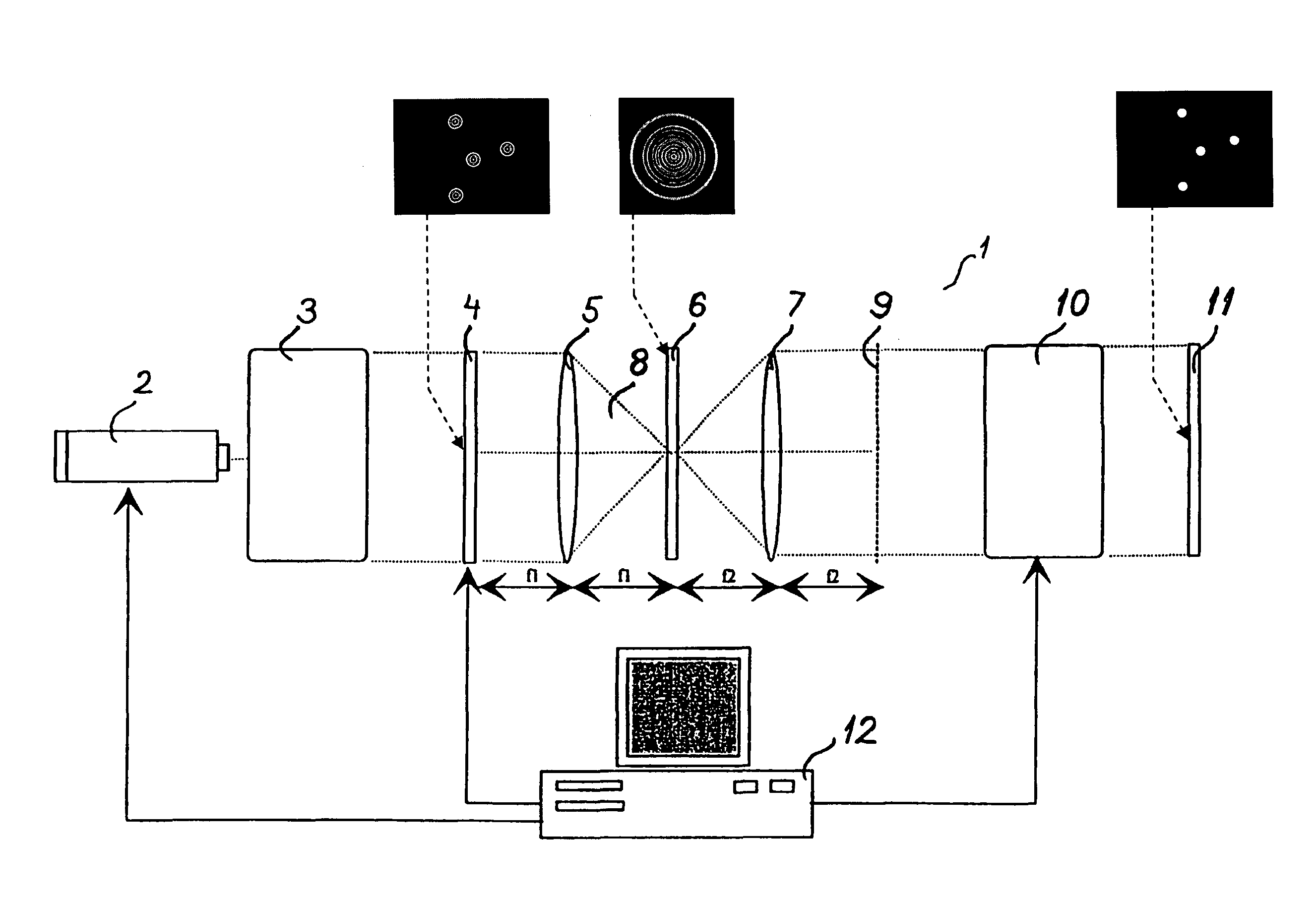
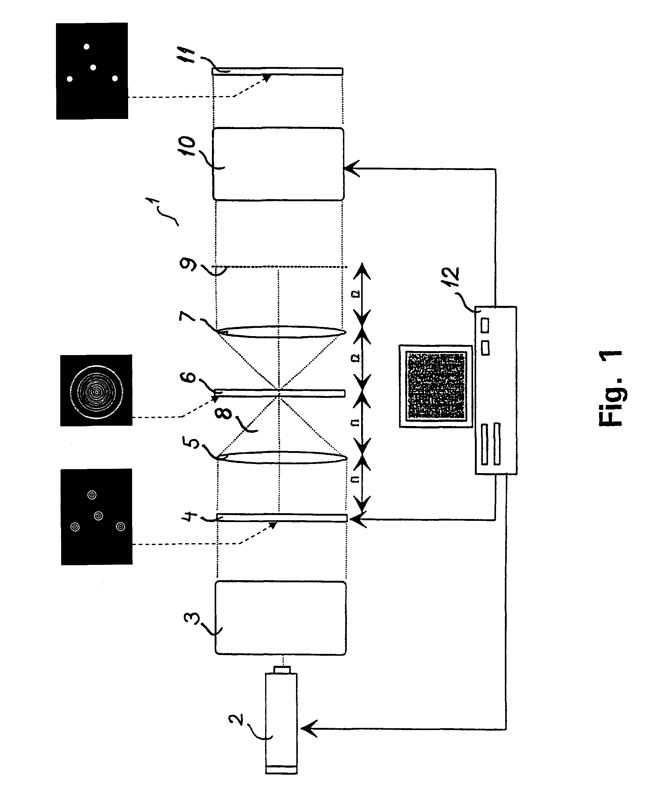
[0083]FIG. 1 shows a 4f imaging system 1. A laser 2 emits a light beam which is expanded by a beam expander 3 into a plane light wave of uniform intensity and directs it towards a second spatial light modulator 4 which in the illustrated embodiment phase and / or amplitude and / or polarisation modulates the incident light. For example, the four exemplary symbols, s, shown at the second spatial light modulator 4, and illustrated in more detail in FIG. 5, ...


PUM


Abstract

A method and system for synthesizing controllable light beams includes a spatially modulated light source that generates electromagnetic radiation with a set of replicas of a predetermined symbol, s, positioned at desired positions (xs, ys) in an object plane o(x, y) intersecting, preferably perpendicular to, the direction of propagation of the electromagnetic radiation, and having spatial amplitudes a(x-xs, y-ys), spatial phases φ(x-xs, y-ys), and spatial polarisation vectors p(x-xs, y-ys), a Fourier transforming lens for Fourier transforming the electromagnetic radiation, a first spatial light modulator for phase shifting the transformed electromagnetic radiation with the phase −Φ(u, v) of S*, S* the complex conjugate of the transformed symbol, a Fourier transforming lens for Inverse Fourier transforming the spatially modulated radiation, a set of light beams are formed propagating through the inverse Fourier plane (x′, y′) at desired positions (x′s, y′s), and a controller for controlling the position of a replica of the symbol, for movement of the light beam.

Description

CROSS REFERENCE TO RELATED APPLICATIONS[0001]This application is the national phase under 35 U.S.C. 371 of PCT International Application No. PCT / DK2007 / 000294 which has an international filing date of Jun. 18, 2007, and also claims priority under 35 U.S.C. 119 to Danish application PA 2006 00834 filed on Jun. 19, 2006, and to U.S. Patent Application No. 60 / 814,553, filed on Jun. 19, 2006, which applications are hereby incorporated by reference in their entirety for all purposes as if fully set forth herein.BACKGROUND OF THE INVENTION[0002]1. Field of the Invention[0003]The invention relates to a method and a system for synthesizing a set of controllable light beams.[0004]2. Description of the Related Art[0005]It is well known to form an image on an illuminated surface of a body by absorption or blocking of energy of an illuminating beam. For example in an overhead projector, an overhead transparent absorbs or blocks part of the light beam of the projector whereby a large image of an...

Claims


Application Information

Patent Timeline
Patent Type & Authority Patents(United States)
IPC IPC(8): G02B27/46
CPCG06E3/00G02B27/52G02B21/32Y10S359/90
Inventor GLUCKSTAD, JESPER
Owner DANMARKS TEKNISKE UNIV
Why Eureka
Try Eureka