A protective fixing structure for computer hardware

A technology of computer hardware and fixed structure, applied in energy-saving computing, recording carrier structural parts, reducing physical parameters of the carrier, etc., can solve the problems of reducing the service life of M. , to avoid the deformation of the PCB substrate, ensure stability and reliability, and avoid thermal stress concentration.

Active Publication Date: 2022-07-12
ANQING NORMAL UNIV
View PDF9 Cites 0 Cited by
  • Summary
  • Abstract
  • Description
  • Claims
  • Application Information

AI Technical Summary

Problems solved by technology

[0002] Computer hardware refers to the general term for various physical devices composed of electronic, mechanical and photoelectric components in a computer system; these physical devices form an organic whole according to the requirements of the system structure to provide a material basis for the operation of computer software; computer hardware usually includes memory , motherboard, graphics card, CPU, hard disk, etc., among which hard disk is an indispensable part of computer storage. With the popularity of solid-state hard disk, solid-state hard disk with M.2 interface is favored by users due to its small size and powerful performance. Among them, NVME solid-state drives are especially popular among mid-to-high-end players due to their excellent read and write performance. However, the main body of the M2 solid-state drive using the NVME protocol is a slender PCB board, and there is no protective device on it. During the process, it is easily affected by the environment inside the chassis, such as dust accumulation, damp, high temperature, etc., and with the increase of speed, the heat generation of solid-state drives is also increasing. Long-term operation at high temperatures will reduce the use of M.2 solid-state drives life and affect the security of data, so it is necessary to design a protective structure that can solve high temperature in a relatively closed device

Method used


Image

  • A protective fixing structure for computer hardware
  • A protective fixing structure for computer hardware
  • A protective fixing structure for computer hardware

Examples


Embodiment Construction

[0019] The application will be described in further detail below in conjunction with the accompanying drawings. It is necessary to point out that the following specific embodiments are only used to further illustrate the application, and should not be construed as limiting the protection scope of the application. Those skilled in the art can The above application content makes some non-essential improvements and adjustments to this application.

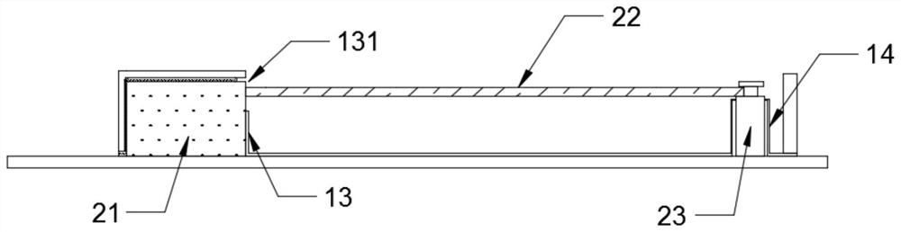
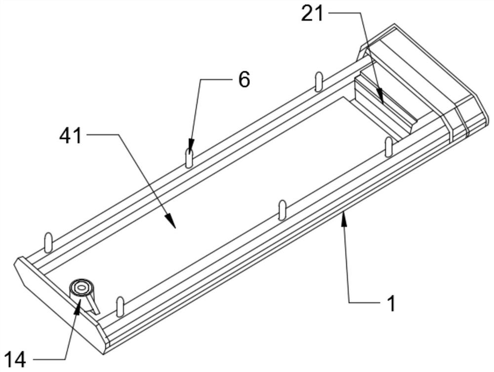
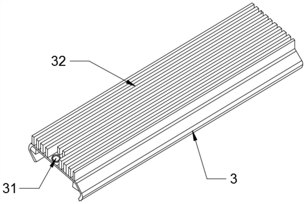
[0020] like Figure 1 to Figure 5 The shown protection and fixing structure for computer hardware includes a casing 1, which is in the shape of a long strip as a whole, and its length spans the solid-state drive slot seat and the solid-state drive fixing column, wherein, in order to facilitate the fixing of the casing, in the One side of the casing 1 is provided with a first cavity 11 that is sleeved on the solid-state drive socket 21 and has an open bottom, and the other side is provided with a second cavity for placing the solid-sta...


PUM


Abstract

The invention relates to a protection and fixing structure for computer hardware, comprising a casing, one side of the casing is provided with a first cavity, the other side is provided with a second cavity, and a space between the first cavity and the second cavity is provided. There is a baffle plate, and the baffle plate is provided with a through hole; the side of the second cavity away from the first cavity is provided with a fixing cylinder that protrudes upward and is used to be sleeved on the fixing column, and the upper cover of the casing is provided with a fixing cylinder for The cover plate that closes the second cavity, the cover plate is concentrically provided with bolt holes at the position close to the fixing cylinder, and the cover plate is also provided with radiating fins; the shell and the cover plate adopted in the present invention can form a relatively closed space , to prevent the dust and moisture in the chassis from continuously infringing on the solid-state drive PCB board, and to ensure the stability and reliability of the solid-state drive. The weight of the body and the cover are not pressed on the solid-state drive PCB board, which will not affect the deformation of the PCB board and ensure the data security in the solid-state drive.

Description

technical field [0001] The invention belongs to the field of computer technology, in particular to the field of protection and fixing structures for computer hardware. Background technique [0002] Computer hardware refers to the general term for various physical devices composed of electronic, mechanical and optoelectronic components in a computer system; these physical devices form an organic whole according to the requirements of the system structure to provide a material basis for the operation of computer software; computer hardware usually includes memory. , motherboard, graphics card, CPU, hard disk, etc. Among them, hard disk is an indispensable part of computer storage. With the popularization of solid-state hard disks, M.2 interface solid-state hard disks are favored by users due to their advantages of small size and powerful performance. Among them, NVME solid-state drives are especially favored by mid-to-high-end players due to their excellent read and write perf...

Claims


Application Information

Patent Timeline
Patent Type & Authority Patents(China)
IPC IPC(8): G11B33/14G11B33/08
CPCG11B33/1446G11B33/1413G11B33/1426G11B33/1486G11B33/08Y02D10/00
Inventor 刘晓飞
Owner ANQING NORMAL UNIV
Why Eureka
Try Eureka