Inner supporting type pipe end face automatic welding and cutting groove machining equipment

A technology for cutting bevels and processing equipment, which is applied in metal processing equipment, turning equipment, turning equipment, etc. It can solve the problems of heavy weight, inconvenience, automatic centering and clamping, and large volume, and achieve the effect of volume and weight reduction

Pending Publication Date: 2021-06-22
上海宝四机械工程有限公司
View PDF0 Cites 4 Cited by
  • Summary
  • Abstract
  • Description
  • Claims
  • Application Information

AI Technical Summary

Problems solved by technology

[0004] The purpose of the present invention is to provide an inner support type pipe end face automatic welding and cutting groove processing equipment, to solve the problem that the existing beveling machines used for pipe beveling are large in size and weight, inconvenient for outdoor mobile operations, and cannot be automatically centered and Disadvantages such as clamping

Method used


Image

  • Inner supporting type pipe end face automatic welding and cutting groove machining equipment
  • Inner supporting type pipe end face automatic welding and cutting groove machining equipment
  • Inner supporting type pipe end face automatic welding and cutting groove machining equipment

Examples


Embodiment 1

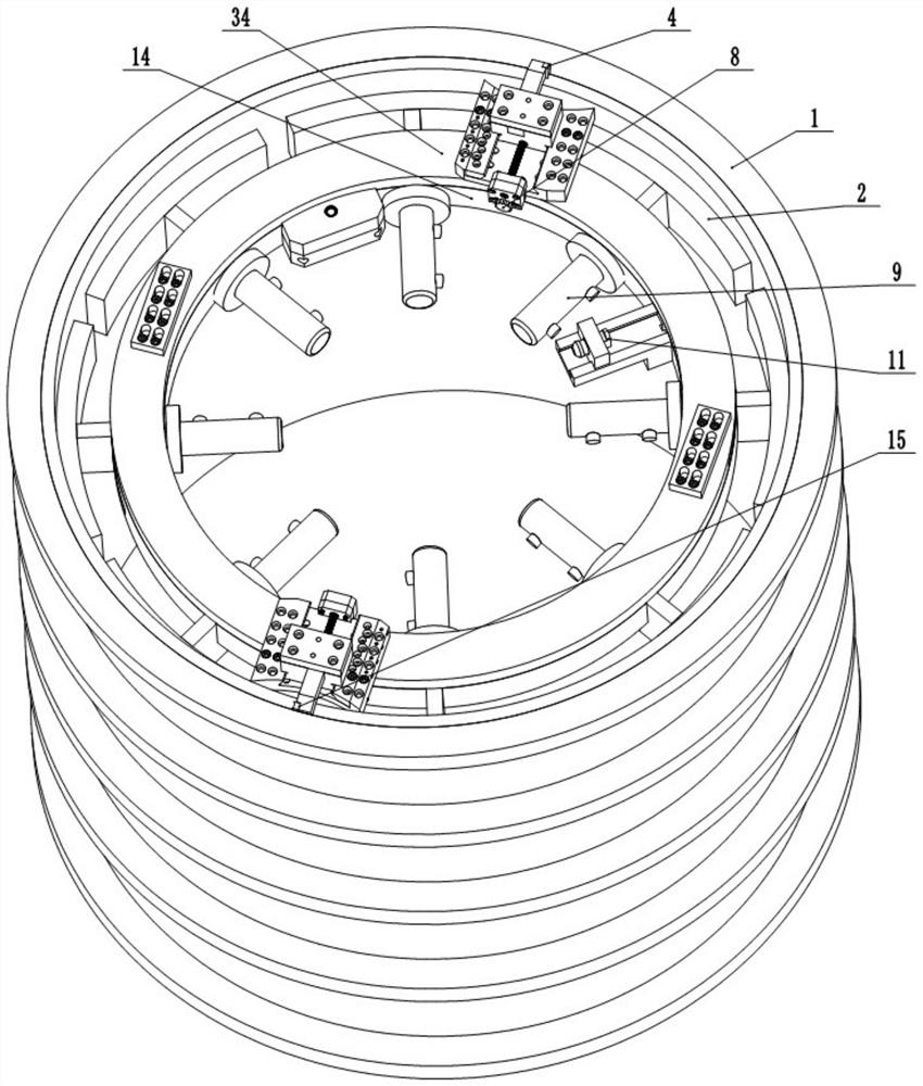
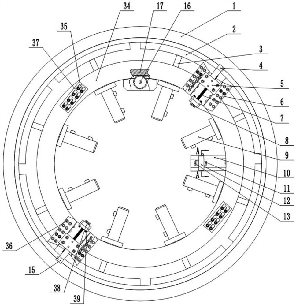
[0033] Embodiment one is basically as attached figure 1 and figure 2Shown: inner support type pipe end face automatic welding and cutting groove processing equipment, including machine body 14, expansion mechanism assembly, rotating toothed disk 17, active transmission mechanism for driving rotating toothed disk 17 and cutting pipe fittings 1 Mechanical cutting actuator for beveling and cutting off pipe fittings 1. The active transmission mechanism includes a motor and a drive gear 16 , the output shaft of the motor is fixedly connected with the drive gear 16 , and the drive gear 16 meshes with the rotary toothed disc 17 . The mechanical cutting executive mechanism includes a groove forming cutting mechanism, a cutting cutting mechanism and an active tool feeding mechanism. Knife rest seat, cut-off knife 15 clamping knife block and cut-off knife 15.

[0034] The body 14 is annular and hollow inside, and the rotating toothed disc 17 is also annular and embedded in the body ...

Embodiment 2

[0050] Embodiment two is basically as attached Figure 4 Shown: the difference between the second embodiment and the first embodiment is that the driving device includes a piston cylinder 20, a piston 22, a compression chamber 19, a sealing compression plate 28, a driving block 31, a rotating screw 29, and a driven pulley 24 and driving pulley 18.

[0051] One end of the expansion block 2 and the expansion adjustment rod 3 is fixedly connected together, and the expansion block 2 and the expansion adjustment rod 3 are hollow inside and communicate with each other, and the side of the expansion block 2 in contact with the inner wall of the pipe fitting 1 , with a number of through holes, the through holes communicate with the expansion block 2, and the through holes are fixed with an airbag cushion 23 for sealing the through holes, the other end of the expansion adjustment rod 3 is connected to one end of the piston 22, and the piston 22 is provided with an air hole, the air ho...


PUM


Abstract

The invention relates to the technical field of machining, in particular to inner supporting type pipe end face automatic welding and cutting groove machining equipment. The inner supporting type pipe end face automatic welding and cutting groove machining equipment comprises a machine body, an expansion mechanism assembly, a rotating fluted disc, a driving transmission mechanism and a mechanical cutting executing mechanism, wherein the machine body is in a circular ring shape and is hollow, the rotating fluted disc is also in a circular ring shape and is installed in the machine body, the top of the machine body is provided with a mounting disc, the mounting disc is fixedly connected with the rotating fluted disc in the machine body, and the mechanical cutting executing mechanism is fixedly installed on the mounting disc; and the expansion mechanism assembly comprises a driving device, expansion adjusting rods and expansion blocks, each expansion block is in a circular arc shape, the radian of one side of each expansion block is consistent with that of the inner wall of a pipe, the other side of each expansion block is fixedly connected with the corresponding expansion adjusting rod, the other ends of the expansion adjusting rods penetrate through the machine body and are connected with the driving device, and the driving device is fixed to the machine body. Therefore, the defects that an existing beveling machine for the pipe is large in size and weight, cannot automatically center and clamp and the like are overcome. The inner supporting type pipe end face automatic welding and cutting groove machining equipment is mainly used for machining the pipe.

Description

technical field [0001] The invention relates to the technical field of mechanical processing, in particular to automatic welding and cutting groove processing equipment for inner-supported pipe end faces. Background technique [0002] During the processing of pipe fittings, especially at the engineering construction site, it is often necessary to cut, cut and bevel the pipe fittings, so as to facilitate the welding of pipe fittings in the next step. The traditional cutting, cutting and beveling of pipe fittings generally adopt lathe turning or oxygen cutting, and need to be ground and welded before welding. However, after the pipe fittings are processed by lathe turning or oxygen cutting, the metal properties of the pipe mouth are easily damaged. This makes the bevel unfavorable for the welding of the pipe fittings in the next step, and because the processing equipment is bulky, heavy and limited by the environment of the construction site, the construction efficiency is gre...

Claims


Application Information

Patent Timeline
Patent Type & Authority Applications(China)
IPC IPC(8): B23B5/16
CPCB23B5/162B23B5/167
Inventor 彭怀江张小军杨占林刘昊天赵亚南
Owner 上海宝四机械工程有限公司
Why Eureka
Try Eureka