Multifunctional dual-motor redundancy braking system and control method

A braking system and dual-motor technology, applied in the field of servo braking systems, can solve problems such as difficulty in satisfying the vehicle's servo braking capacity and the inability of a single electro-hydraulic servo brake solution, to facilitate function expansion, optimize brake pressure distribution, The effect of reducing loss

Pending Publication Date: 2021-06-22
南京经纬达汽车科技有限公司
View PDF0 Cites 5 Cited by
  • Summary
  • Abstract
  • Description
  • Claims
  • Application Information

AI Technical Summary

Problems solved by technology

[0015] The purpose of the present invention is to solve the problem that the vacuum booster assembly scheme and the single electro-hydraulic servo brake scheme in the prior art cannot or are difficult to meet the servo braking capacity of vehicles with a higher design tonnage, and propose a multi-functional dual-motor redundant brake System and its control method

Method used


Image

  • Multifunctional dual-motor redundancy braking system and control method
  • Multifunctional dual-motor redundancy braking system and control method
  • Multifunctional dual-motor redundancy braking system and control method

Examples


Embodiment 1

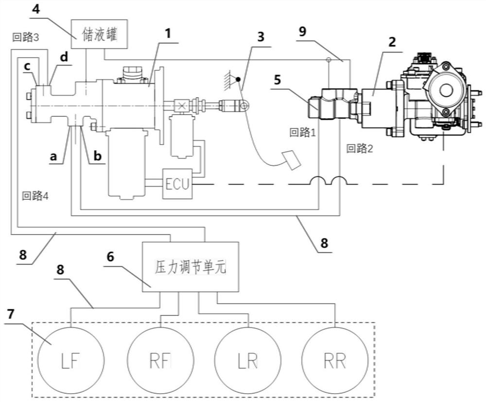
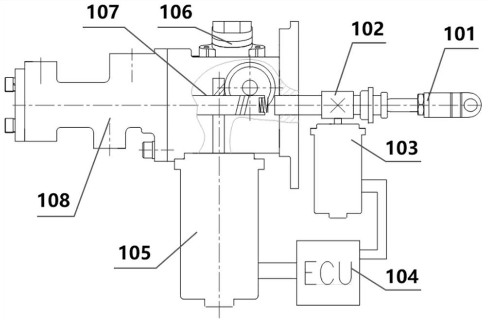
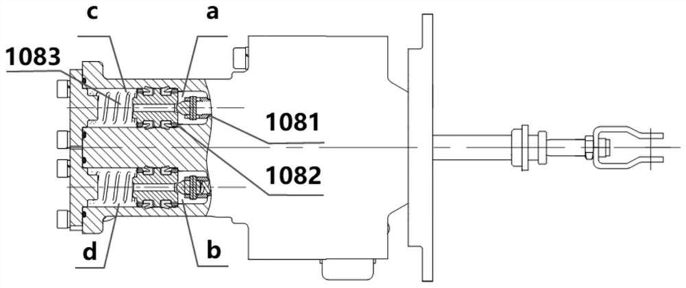
[0067] Please refer to Figure 1 to Figure 4 , this embodiment provides a multifunctional dual-motor redundant braking system, which mainly includes a main electro-hydraulic servo brake assembly 1, an auxiliary electro-hydraulic servo brake assembly 2, a brake pedal assembly 3, and a liquid storage tank 4 , brake master cylinder 5, pressure regulating unit 6 and brake group 7. Among them: the main electro-hydraulic servo brake assembly 1 and the auxiliary electro-hydraulic servo brake assembly 2 are connected through CAN bus communication, and the two ends of the main electro-hydraulic servo brake assembly 1 are respectively connected to the brake pedal assembly 3 and The parallel master cylinder 108 is connected, and the auxiliary electro-hydraulic servo brake assembly 2 is connected with the brake master cylinder 5 .

[0068] In this embodiment, the fluid storage tank 4 is used to provide brake fluid to the brake master cylinder 5 and the parallel master cylinder 108 . The...

Embodiment 2

[0112] The structure of the dual-motor redundant braking system in this embodiment is basically the same as in Embodiment 1, the difference being that: the first brake set in this embodiment is composed of a left rear wheel brake LR and a right rear wheel brake RR; The brake group is composed of left front wheel brake LF and right front wheel brake RF. The four oil outlets of the pressure regulating unit 6 are respectively connected with LR, RR, LF and RF. At this time, the braking system is an H-shaped arrangement.

Embodiment 3

[0114]The structure of the dual-motor redundant braking system in this embodiment is basically the same as that in Embodiment 1, the difference being that the first brake group in this embodiment consists of a left front wheel brake LF and a right rear wheel brake RR, and the second The brake group consists of the right front wheel brake RF and the left rear wheel brake LR. The four oil outlets of the pressure regulating unit 6 are respectively connected with LF, RR, RF and LR. At this time, the brake system is an X-shaped arrangement.


PUM


Abstract

The invention provides a multifunctional dual-motor redundancy brake system and a control method. The brake system mainly comprises a brake pedal assembly, a main electro-hydraulic servo brake assembly, an auxiliary electro-hydraulic servo brake assembly, a liquid storage tank, a parallel main cylinder, a brake main cylinder, a hydraulic adjusting unit and a brake set. The two sides of the main electro-hydraulic servo brake assembly are connected with the brake pedal and the parallel connection main cylinder respectively. The auxiliary electro-hydraulic servo assembly is connected with a brake master cylinder, and the mechanical assembly is provided with a self-locking mechanism and can achieve power-off locking. An oil outlet of the brake master cylinder is connected with two oil inlets of the parallel brake master cylinder through two loops respectively, and two oil outlets of the parallel brake master cylinder are connected with a left oil inlet and a right oil inlet of the pressure adjusting unit through the two loops respectively. According to the brake system, multiple working modes such as brake-by-wire brake with brake keeping, external request brake, brake energy recovery assistance and manpower backup brake can be achieved, multiple redundant brake modes are achieved, the brake requirement of a high-tonnage vehicle can be met, and the safety of the vehicle is improved.

Description

technical field [0001] The invention belongs to the technical field of automobile braking, and in particular relates to a servo braking system in a hydraulic braking system. Background technique [0002] According to the transmission mode of braking energy, automobile braking system can be divided into mechanical type, hydraulic type, pneumatic type, electromagnetic type and so on. Among them, the braking energy transmission mode of the hydraulic braking system is hydraulic pressure, that is, the hydraulic pressure is increased by compressing the brake fluid in the braking system during braking. After the hydraulic pressure is transmitted to the wheel brake, it will finally push the friction plate to stick to the brake The disc or brake drum produces a braking torque that hinders the rotation of the wheel, and finally the ground reacts on the wheel with a ground braking force that is opposite to the direction of travel to brake the vehicle. [0003] Compared with the pneuma...

Claims


Application Information

Patent Timeline
Patent Type & Authority Applications(China)
IPC IPC(8): B60T13/14B60T13/66
CPCB60T13/142B60T13/148B60T13/66
Inventor 丁能根史晓波邓伟文
Owner 南京经纬达汽车科技有限公司
Why Eureka
Try Eureka