

Ground construction tamping equipment for automobile square construction
A technology for squares and automobiles, applied in the field of ground construction compaction equipment, can solve the problems of entry and pragmatism inside the machine, and achieve the effects of scientific and reasonable structure, safe and convenient use, and increased service life.
- Summary
- Abstract
- Description
- Claims
- Application Information
AI Technical Summary
Problems solved by technology
Method used
Image

Examples
Embodiment Construction
[0028] The preferred embodiments of the present invention will be described below in conjunction with the accompanying drawings. It should be understood that the preferred embodiments described here are only used to illustrate and explain the present invention, and are not intended to limit the present invention.
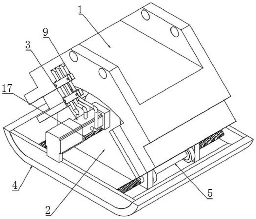
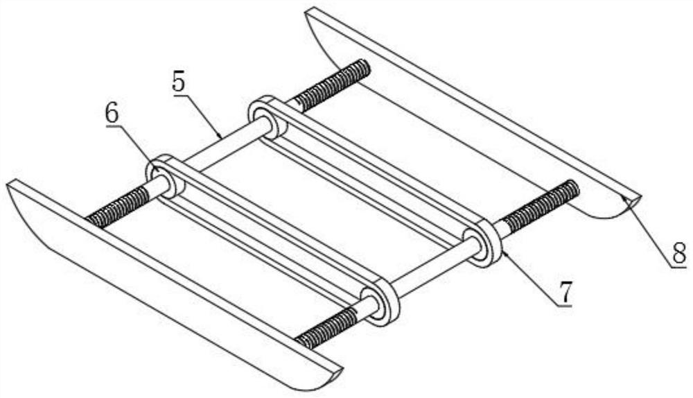
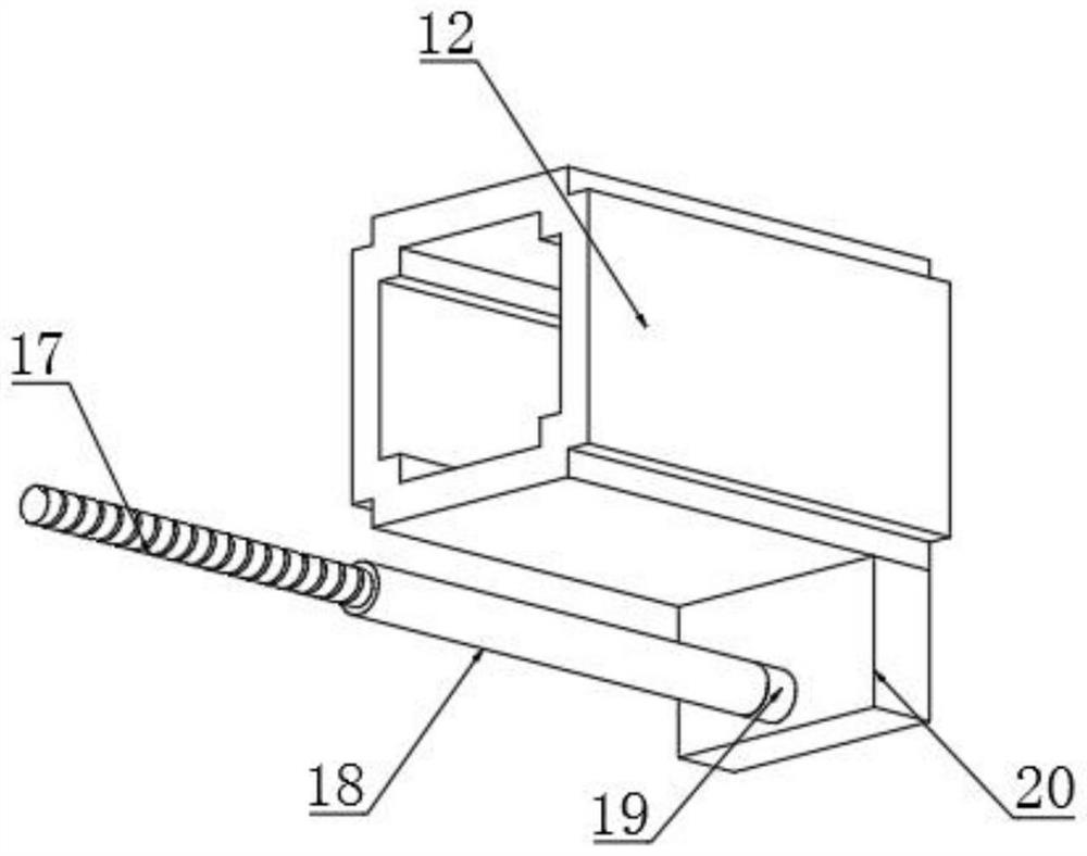
[0029] Example: such as Figure 1-4 As shown, the present invention provides a technical solution for ground construction tamping equipment for the construction of an automobile plaza, including a connecting seat 1, a shock absorbing seat 2 connected to the middle of the bottom end of the connecting seat 1, and a vibration damping seat 2 is fixedly installed in the middle of one end of the shock absorbing seat 2. The motor 3, the input end of the vibration motor 3 is electrically connected to the output end of the mains, and the vibration motor 3 and the shock absorber 2 are connected by a screw, which can facilitate the operation of the vibration motor 3 and reduce ...
PUM
 Abstract
Description
Claims
Application Information