
Ground source heat exchange well backfilling device capable of tamping well bottom and well wall

A technology of ground source heat exchange and well wall, applied in geothermal energy power generation, heat collectors using groundwater as working fluid, buildings, etc., can solve the problems of slurry vacancy, heat exchange efficiency reduction, accumulation at the bottom of wells, etc. , to achieve the effect of reducing the probability of air bubbles and reducing the degree of slurry leakage

Inactive Publication Date: 2021-06-22
马东标
View PDF0 Cites 0 Cited by
  • Summary
  • Abstract
  • Description
  • Claims
  • Application Information

AI Technical Summary

Problems solved by technology

[0005] In order to overcome the existing technology, one of the ground source heat pumps needs to be drilled to form a heat exchange well, and then put the U-shaped tube into the heat exchange well, and then use special slurry to backfill the heat exchange well. Workers use When the pump transports the slurry to the heat exchange well, there will be slurry faults and low efficiency. At the same time, after the hole is turned, some sediment will accumulate at the bottom of the well. After the U-shaped tube is put in, the lower part of the U-shaped tube will bend Phenomenon, resulting in low heat transfer efficiency at some parts of the U-shaped tube. At the same time, some well wall soil is relatively loose. After the slurry is poured into the heat exchange well, part of the slurry will penetrate into the loose tube wall, resulting in local slurry vacancies. , that is, the slurry in the heat exchange well has the phenomenon of air bubbles, which greatly reduces the heat exchange efficiency. The purpose of this invention is to provide a ground source heat exchange well backfill device that can tamp the bottom and the well wall

Method used


Image

  • Ground source heat exchange well backfilling device capable of tamping well bottom and well wall
  • Ground source heat exchange well backfilling device capable of tamping well bottom and well wall
  • Ground source heat exchange well backfilling device capable of tamping well bottom and well wall

Examples


Embodiment 1

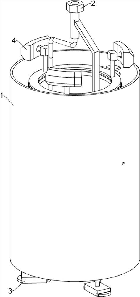
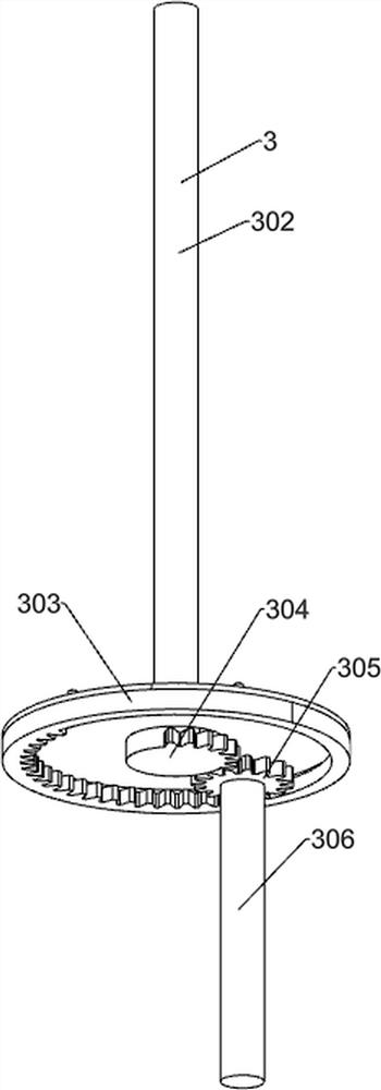
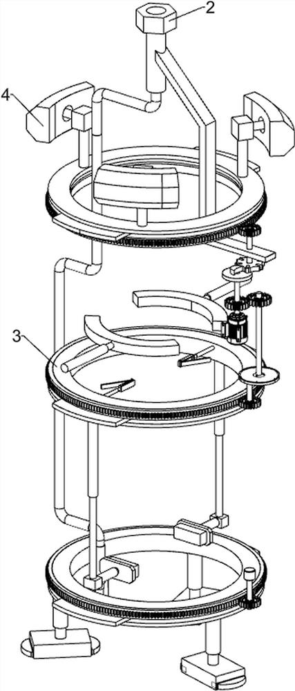
[0031] A ground source heat exchange well backfill device capable of tamping well bottom and well wall, such as Figure 1-10 As shown, it includes a first support frame 1, a transportation component 2, a bottom hole treatment component 3 and a well wall treatment component 4; the first support frame 1 is connected to the transportation component 2; the first support frame 1 is connected to the bottom hole treatment component 3 The first support frame 1 is connected with the well wall processing assembly 4; the transportation assembly 2 is connected with the well wall processing assembly 4; the bottom hole processing assembly 3 is connected with the well wall processing assembly 4.

[0032] Working principle: When preparing for work, connect the external hose to the transportation component 2, insert the tail of the U-shaped tube into the device, make the U-shaped tube penetrate the device, and then put the device vertically into the heat exchange well to make the bottom of the ...


PUM


Abstract

The invention relates to the field of heat exchange well backfilling, and particularly relates to a ground source heat exchange well backfilling device capable of tamping a well bottom and a well wall. The ground source heat exchange well backfilling device capable of tamping the well bottom and the well wall comprises a first supporting frame, a transportation assembly, a well bottom treatment assembly and a well wall treatment assembly; the first supporting frame is connected with the transportation assembly; the first supporting frame is connected with the well bottom treatment assembly; the transportation assembly is connected with the well wall treatment assembly; and the well bottom treatment assembly is connected with the well wall treatment assembly. According to the ground source heat exchange well backfilling device capable of tamping the well bottom and the well wall, silt at the bottom of a heat exchange well is automatically tamped downwards during use, so that a U-shaped pipe head pipeline is vertically located in the heat exchange well, meanwhile, slurry is automatically and fully filled into the well bottom, the well wall is automatically tamped towards the outer side, the slurry exosmosis degree is reduced, and therefore the probability of bubbles is reduced.

Description

technical field [0001] The invention relates to the field of backfilling of heat exchange wells, in particular to a backfilling device for ground source heat exchange wells capable of compacting well bottoms and well walls. Background technique [0002] The ground source heat pump is a heating central air conditioning system composed of a water ground source heat pump unit, a geothermal energy exchange system, and a building system, which uses rock and soil, stratum soil, groundwater or surface water as a low-temperature heat source. According to the different forms of geothermal energy exchange systems, ground source heat pump systems are divided into buried pipe ground source heat pump systems, groundwater ground source heat pump systems and surface water ground source heat pump systems. [0003] In the prior art, one of the ground source heat pumps needs to be drilled to form a heat exchange well first, then the U-shaped tube is put into the heat exchange well, and then t...

Claims


Application Information

Patent Timeline
Patent Type & Authority Applications(China)
IPC IPC(8): E02D15/04F24T10/20
CPCE02D15/04F24T10/20Y02E10/10
Inventor 马东标
Owner 马东标
Learn More