Conveying pipeline sealing structure

A technology of sealing structure and conveying pipeline, which is used in pipeline protection, engine sealing, pipeline damage/wear prevention, etc. Squeeze and bond flanges, prolong service life and prevent local wear

Pending Publication Date: 2021-06-22
江苏西沙科技有限公司
View PDF6 Cites 0 Cited by
  • Summary
  • Abstract
  • Description
  • Claims
  • Application Information

AI Technical Summary

Problems solved by technology

[0004] After practical application, the service life is found; (1) It is inevitable to collide during the installation process. The rubber hose, especially the large-diameter self-floating hose, is very heavy, and the impact force is very strong. It is easy to damage the sealant and damage the sealant. If it is not replaced, it will be damaged soon (2) During the installation process, the gasket and the flange surface glue must be tightened by bolts to squeeze the sealant, and there will be arching of the sealant on the inner wall between the pipes, which will be later If the pipeline is worn first, there will be a damaged gap, which will cause local over-grinding and affect the service life; (3) The thickness of the gasket or flange surface glue is generally about 8 to 10mm, and after a period of use, it will produce permanent deformation. Especially under increasing working pressure, it will be more obvious, which will reduce the sealing effect of the sealant and cause leakage hazards; (4) The gasket or flange surface glue needs to be removed after a project is completed, due to long-term Squeeze, some surface glue will stick to the flange, it is not easy to disassemble, need to use external force to separate, it will damage the sealant, the sealant needs to be replaced when reinstalling, and the flange surface glue needs to be repaired, which will be very troublesome
(5) Under the development situation of large-diameter ultra-high pressure, it has gradually failed to meet the requirements of new rubber hose sealing

Method used


Image

  • Conveying pipeline sealing structure
  • Conveying pipeline sealing structure
  • Conveying pipeline sealing structure

Examples


Embodiment Construction

[0026] The conveying pipe sealing structure of the present invention will be further described in detail below with reference to the accompanying drawings and specific embodiments.

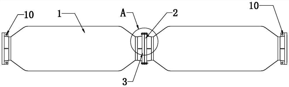
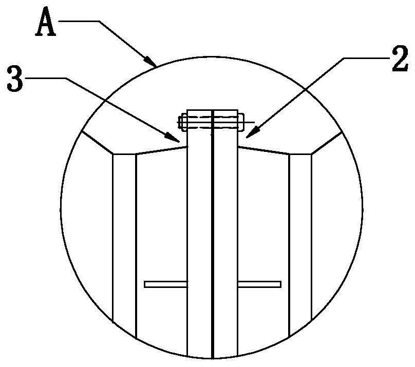
[0027] As shown, the delivery pipe sealing structure of the present invention is mainly used to self-floating tubes, of course, the products of other hoses, similar interfaces can be used to use this technical solution, which includes tubes 1. The sealing flange 2 and the docking flange 3 are provided on both ends, and the lifting tuning 10 is added to the sealing flange 2 and the docking flange 3 after the need for the self-floating tube, and the flange 3 has a smooth outer side. End face, of course, the outer end surface of the sealing flange 2 is also a smooth surface, and the flatness must be less than 2mm, the sealing flange 2 and the docking flange need to take a chamfer 1-1-2 to reduce sharpness, to avoid hidden dangers,

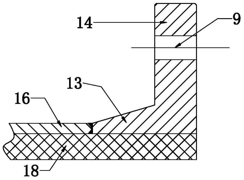
[0028] The outer end surface of the sealing flange 2 is opened with an a...


PUM


Abstract

The invention discloses a conveying pipeline sealing structure. The conveying pipeline sealing structure comprises a sealing flange and a butt joint flange which are arranged at the two ends of a pipe body, wherein the butt joint flange has a smooth outer side end face; an outer side end face of the sealing flange is provided with an annular sealing groove used for accommodating a linear sealing ring; the annular sealing groove is provided with a groove formed by the fact that the width size of an opening end is smaller than the width size of the inner bottom; a linear sealing ring is arranged in the annular sealing groove and can be limited in the annular sealing groove through the groove; and the sealing flanges and the butt joint flanges of the adjacent pipe bodies can be fixedly connected through fasteners after being in butt joint. The conveying pipeline sealing structure has the advantages that the sealing is easier and more durable under the same force, the collision is not easy to occur in the mounting process, the sealant is prevented from being damaged by collision, the hidden danger of leakage is eliminated, the problem of local wear is completely solved, the service life is prolonged, the problems of deformation generated in the use process and long-term extrusion and bonding of the flanges are also solved, the hidden danger of leakage is further eliminated, and the maintenance is convenient.

Description

Technical field [0001] The present invention relates to a sealing technique of a conveying conduit in a dredging engineering, in particular to a conveying pipe sealing structure. Background technique [0002] Dredging rubber hoses currently except for some small dredgers of small diameters, the use of an extension, and the straight rubber is substantially used in the use of metal flanges, and the seal between the connected metal flange is mainly through rubber. According to the rubber of this sealing, the rubber is mainly divided into independent rubber gaskets, and the flange sulfur is integrated with a full-flanged and only half-flanged collide below the screw hole, and the rubber gasket is mainly used in small calibrators. ( The following), while the large-diameter rubber hose is basically adopted with flange sulfur, which is beautiful, practical, and convenient installation. [0003] With the rapid development of dredging dredgers, the efficiency of efficiency, the diameter ...

Claims


Application Information

Patent Timeline
Patent Type & Authority Applications(China)
IPC IPC(8): F16L33/28F16L33/18F16L57/06F16J15/10
CPCF16L33/28F16L33/18F16L57/06F16J15/102F16J15/108
Inventor 张志勇
Owner 江苏西沙科技有限公司
Why Eureka
Try Eureka