Drying room with dry and wet gas separation function

A technology of drying room and function, applied in the field of drying room, can solve the problems of inability to separate dry and wet gas, increase energy consumption, increase drying cost, etc., so as to improve drying efficiency and drying uniformity, improve drying The effect of utilization and simple structure

Pending Publication Date: 2021-06-22
山东瑞海自动化科技有限公司
View PDF0 Cites 1 Cited by
  • Summary
  • Abstract
  • Description
  • Claims
  • Application Information

AI Technical Summary

Problems solved by technology

[0002] The drying room is a kind of drying equipment that has been widely used for many years. It is mainly used for drying agricultural products, food, wood, and medicinal materials. The structure of the existing drying room roughly includes a rectangular box, a blowing device and The heating device and the blowing device keep the air in the box circulating, and the heating device keeps the air heated, so as to continuously dry the products in the drying room. However, the drying room with this structure mainly has the following disadvantages : After baking for a period of time, the air moisture in the box will reach a certain humidity. At this time, it is necessary to open the moisture outlet and air inlet of the box to perform moisture removal and ventilation operations, and then the hot air with excessive humidity in the box will However, the dehumidification and ventilation operation usually cannot realize the separation of dry and wet gases. When dehumidifying, most of the hot air in the box will be discharged at the same time, which increases energy consumption and increases drying costs.

Method used


Image

  • Drying room with dry and wet gas separation function
  • Drying room with dry and wet gas separation function
  • Drying room with dry and wet gas separation function

Examples


Embodiment Construction

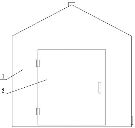
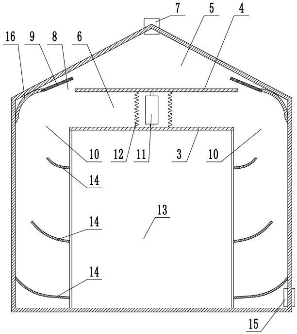
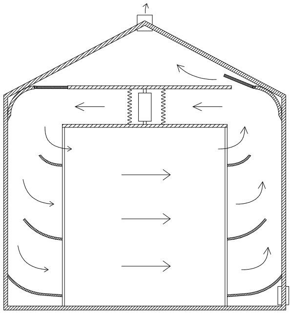
[0024] Referring to the accompanying drawings, the drying room with the function of separating dry and wet gas includes a box body 1 roughly in the shape of a cuboid. The front and rear lengths of the box body 1 are greater than the left and right widths. Door 2, secondly, in the box body 1, be provided with the middle partition 3 that box body 1 inner cavity is divided into the upper chamber and the lower chamber, the space of the lower chamber is greater than the space of the upper chamber, in addition, in the upper chamber There is an upper partition 4 that separates the upper chamber into an upper moisture accumulation chamber 5 and a lower blast chamber 6. Secondly, in order to perform moisture removal and ventilation, the top of the moisture accumulation chamber 5 is provided with a humidifier. The moisture discharge port 7 for air discharge, the damp discharge port 7 can be equipped with a damper and a fan to block the moisture discharge port 7 as required, and the lower...


PUM


Abstract

The invention discloses a drying room with dry and wet gas separation function. The drying room comprises a box body; a box opening and a box door for sealing the box opening are arranged at the front end of the box body; a middle partition plate for dividing an inner cavity of the box body into an upper cavity body and a lower cavity body is arranged in the box body; an upper partition plate for dividing the upper cavity body into an upper moisture gathering chamber and a lower blast chamber is arranged in the upper cavity body; a moisture discharging opening is formed in the top of the moisture gathering chamber; the left side portion and right side portion of the upper partition plate are each provided with a vertically-through ventilation opening and a sealing door capable of controlling opening and closing of the ventilation opening; air inlets and outlets are formed in the left side portion and right side portion of the middle partition plate; and an air heating device and an air blowing device which is capable of achieving forward or reverse alternate air blowing are installed in the blast chamber. According to the drying room, hot air with high humidity is selectively exhausted in the moisture removal and air exchange process, then the utilization efficiency of the hot air can be improved, the energy consumption can be reduced, the structure is simple and ingenious, and the drying efficiency and the drying uniformity can be improved.

Description

technical field [0001] The invention relates to a drying room capable of automatically separating dry and wet gas. Background technique [0002] The drying room is a kind of drying equipment that has been widely used for many years. It is mainly used for drying agricultural products, food, wood, and medicinal materials. The structure of the existing drying room roughly includes a rectangular box, a blower device and The heating device and the blowing device keep the air in the box circulating, and the heating device keeps the air heated, so as to continuously dry the products in the drying room. However, the drying room with this structure mainly has the following disadvantages : After baking for a period of time, the air moisture in the box will reach a certain humidity. At this time, it is necessary to open the moisture outlet and air inlet of the box to perform moisture removal and ventilation operations, and then make the hot air with high humidity in the box However, t...

Claims


Application Information

Patent Timeline
Patent Type & Authority Applications(China)
IPC IPC(8): F26B9/02F26B21/00F26B21/04F26B25/00
CPCF26B9/02F26B21/001F26B21/004F26B21/04F26B25/00
Inventor 张培森
Owner 山东瑞海自动化科技有限公司
Why Eureka
Try Eureka