
Infrared thermal imaging target tracking temperature measurement method capable of avoiding jitter interference

A technology of infrared thermal imaging and target tracking, applied in radiation pyrometry, image enhancement, image analysis and other directions, can solve the problems of temperature measurement target easily leaving the ROI area, affecting the accuracy of temperature measurement, and taking a long time. The effect of background temperature interference, avoiding temperature measurement failure, and accurate target temperature

Pending Publication Date: 2021-06-22
武汉智谱科技有限公司
View PDF0 Cites 0 Cited by
  • Summary
  • Abstract
  • Description
  • Claims
  • Application Information

AI Technical Summary

Problems solved by technology

[0003] Due to the irregularity of the target imaging boundary, after manually setting rectangular, circular, and elliptical regular ROIs, since the ROI area generally contains part of the background area, the parameters such as the highest temperature, the lowest temperature, and the average temperature of the measurement target cannot accurately reflect the target. the real temperature of
Manually setting the polygonal ROI and enclosing the measured target with line segment connections is not only difficult to completely match the target edge accurately, but also easy to form glitches, and it takes a long time and is inefficient
When using a handheld infrared temperature measurement device, affected by hand shake, the temperature measurement target is easy to leave the ROI area, which brings great inconvenience to use and affects the accuracy of temperature measurement

Method used


Image

  • Infrared thermal imaging target tracking temperature measurement method capable of avoiding jitter interference
  • Infrared thermal imaging target tracking temperature measurement method capable of avoiding jitter interference
  • Infrared thermal imaging target tracking temperature measurement method capable of avoiding jitter interference

Examples


Embodiment Construction

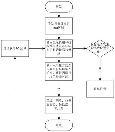
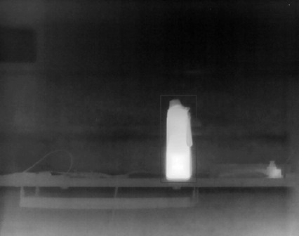
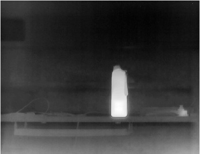
[0037] The present invention first defines the range with a regular shape, and performs target edge detection to extract the initial contour. In order to prevent the target outer contour edge from forming a closed area, the outer contour of the target is obtained by the scanning method as the initial contour of the level set; then the active contour algorithm is used. Realize the precise and automatic positioning of the contour, simple operation and accurate positioning. This ensures accurate target temperature and eliminates background temperature interference. The method of the invention is used to track the target in real time and update the precise closed area of ​​the target in time, which can avoid temperature measurement failure caused by hand shaking when using a portable infrared temperature measurement device, and can also avoid temperature measurement failure caused by the movement of the temperature measurement target.

[0038] Specific embodiments of the present i...


PUM


Abstract

The invention discloses an infrared thermal imaging target tracking temperature measurement method and system capable of avoiding jitter interference. The method comprises the following steps: S1, manually selecting a regular ROI region close to a target contour on a target image; S2, carrying out edge detection on a target in the ROI region, extracting an edge contour and texture details, and acquiring a closed target contour from the edge contour by using a scanning filling method; S3, taking the target contour obtained in the step S2 as an initial curve of a level set, discretizing the initial curve, combining the discretized initial curve and the target image, and performing iteration by using an active contour model based on the level set to obtain an accurate target area; and S4, counting the temperature value in the target area obtained in the step S3, and obtaining the highest temperature, the lowest temperature and the average temperature of the target. According to the invention, the temperature measurement failure caused by hand shaking when the portable infrared temperature measurement equipment is used can be avoided; and the temperature measurement failure caused by the movement of the temperature measurement target can be avoided.

Description

technical field [0001] The invention belongs to the technical field of optical parameter measurement, and in particular relates to a temperature measurement method and system for infrared thermal imaging target tracking that can avoid shaking interference. Background technique [0002] At present, the application of infrared thermal imaging in the temperature measurement industry is becoming more and more popular. The measured targets can be people, animals, vehicles, electrical equipment, etc. Due to the irregular imaging shape of the temperature measurement target, it is often necessary for the user of the infrared thermal imager to manually set the imaging area of ​​the target to be measured, which is usually called setting a region of interest (ROI for short). There are usually rectangle, circle, ellipse, polygon and other types for users to choose for setting the shape of the ROI area. Then measure parameter information such as the highest temperature, the lowest tempe...

Claims


Application Information

Patent Timeline
IPC IPC(8): G01J5/00G06T7/13
CPCG01J5/00G06T7/13G01J2005/0077G06T2207/10048G06T2207/20104
Inventor 孙国强
Owner 武汉智谱科技有限公司
Features
  • Generate Ideas
  • Intellectual Property
  • Life Sciences
  • Materials
  • Tech Scout
  • Unparalleled Data Quality
  • Higher Quality Content
  • 60% Fewer Hallucinations
Learn More