Antenna plate and antenna system

An antenna board and dielectric substrate technology, applied in the field of antennas, can solve the problems of antenna board explosion, thin board damage, thin parasitic radiation layer, etc., and achieve the effect of widening beam width, improving antenna performance and reducing cost

Pending Publication Date: 2021-06-22
CHENGDU T-RAY TECH CO LTD
View PDF6 Cites 0 Cited by
  • Summary
  • Abstract
  • Description
  • Claims
  • Application Information

AI Technical Summary

Problems solved by technology

[0003] Because there is a closed cavity in the antenna board, it is easy to cause the antenna board to explode when heated, so traditional hot pressing cannot be realized, let alone reflow soldering, and there will be a series of reliability problems in the later stage of the product, and many antenna designs The thickness of the pa

Method used


Image

  • Antenna plate and antenna system
  • Antenna plate and antenna system
  • Antenna plate and antenna system

Examples


Example Embodiment

[0027] In order to make the objects, technical solutions, and advantages of the present invention more clearly, the technical solutions in the embodiments of the present invention will be described in contemplation in the embodiments of the present invention, and will be described, and the embodiments described in the embodiments of the present invention will be described. It is a part of the embodiments of the present invention, not all of the embodiments. Components of the embodiments of the present invention described and illustrated in the drawings herein can be arranged and designed in various configurations.

[0028] Thus, the following detailed description of the embodiments of the invention as provided in the drawings are not intended to limit the scope of the invention, but only the selected embodiments of the present invention are shown. Based on the embodiments of the present invention, those of ordinary skill in the art will belong to the scope of the present invention...


PUM


Abstract

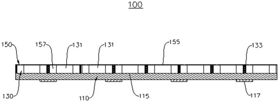
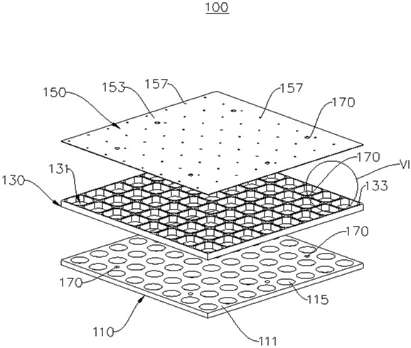
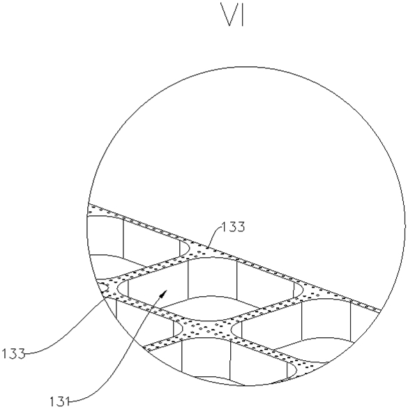
The invention provides an antenna plate and an antenna system, and relates to the technical field of antennae. The antenna plate comprises a main radiation plate, a dielectric substrate and a parasitic radiation plate, and the dielectric substrate is arranged between the main radiation plate and the parasitic radiation plate; the dielectric substrate is provided with a plurality of air cavities, the parasitic radiation plate is provided with a plurality of air guide holes, the positions of the air guide holes are in one-to-one correspondence with the positions of the air cavities, and the air guide holes are used for realizing circulation of air in the air cavities and external air. The air cavity is arranged on the antenna plate, the dielectric constant of the antenna is reduced, the antenna loss is reduced, the antenna performance is improved, and the cost is reduced; and the air guide hole design is added to change the closed air cavity into a semi-open type, so the problem of plate explosion caused by heating is solved, and the whole air cavity structure is more stable and reliable. In addition, the air cavity provided by the invention is additionally provided with a shielding ground hole design, so that isolation between different air cavity units can be realized, and the air cavity can also be used for widening the unit beam width.

Description

technical field [0001] The present invention relates to the technical field of antennas, in particular to an antenna board and an antenna system. Background technique [0002] The high-speed communication technology requires that the printed circuit board (PCB) has the characteristics of small transmission loss, short transmission delay time, and small signal transmission distortion, which makes the materials used for antenna boards need to have excellent dielectric properties. The dielectric constant of air (1.00053) is second only to the dielectric constant under vacuum. Therefore, if an air cavity can be installed in the antenna board, the transmission loss can be minimized and high-quality signal transmission can be achieved. [0003] Because there is a closed cavity in the antenna board, it is easy to cause the antenna board to explode when heated, so traditional hot pressing cannot be realized, let alone reflow soldering, and there will be a series of reliability probl...

Claims


Application Information

Patent Timeline
IPC IPC(8): H01Q1/38H01Q1/36
CPCH01Q1/36H01Q1/38
Inventor 徐豪陈智慧周锐李勇
Owner CHENGDU T-RAY TECH CO LTD
Why Eureka
Try Eureka