
Bidirectional beam forming leaky-wave antenna and power divider loaded antenna assembly

A leaky wave antenna and beamforming technology, applied in the field of antenna components, can solve problems such as reducing system efficiency

Active Publication Date: 2021-06-22
BEIJING JIAOTONG UNIV
View PDF10 Cites 4 Cited by
  • Summary
  • Abstract
  • Description
  • Claims
  • Application Information

AI Technical Summary

Problems solved by technology

All of these problems reduce the efficiency of the system

Method used


Image

  • Bidirectional beam forming leaky-wave antenna and power divider loaded antenna assembly
  • Bidirectional beam forming leaky-wave antenna and power divider loaded antenna assembly
  • Bidirectional beam forming leaky-wave antenna and power divider loaded antenna assembly

Examples


Embodiment Construction

[0050] Embodiments of the present invention are described in detail below, examples of which are shown in the drawings, wherein the same or similar reference numerals denote the same or similar elements or elements having the same or similar functions throughout. The embodiments described below by referring to the figures are exemplary only for explaining the present invention and should not be construed as limiting the present invention.

[0051] Those skilled in the art will understand that unless otherwise stated, the singular forms "a", "an", "said" and "the" used herein may also include plural forms. It should be further understood that the word "comprising" used in the description of the present invention refers to the presence of said features, integers, steps, operations, elements and / or components, but does not exclude the presence or addition of one or more other features, Integers, steps, operations, elements, components, and / or groups thereof. It will be understoo...


PUM


Abstract

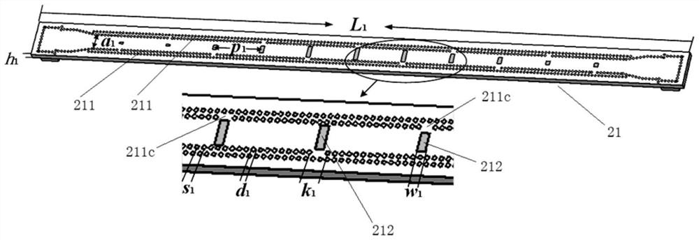
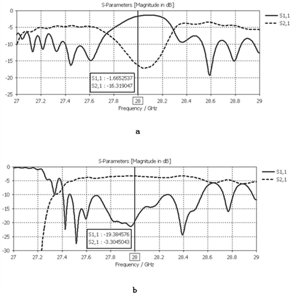
The invention discloses a bidirectional beamforming leaky-wave antenna and a power divider loaded antenna assembly. SIW LWA units with symmetrical double beams are adopted for arraying, the length of the gap of the aperture surface of each unit is designed to meet binomial distribution, and the gap widths of the two units are different, and a substrate integrated waveguide side wall opening with a stop band self-suppression function is designed; the larger the local inductance needs to be reduced, the larger the opening of the side wall of the corresponding substrate is; the Z-shaped anti-phase unequal power divider is used for providing two paths of excitation sources of which the phase difference is 180 degrees and the power ratio is 1: 5. According to the leaky-wave antenna provided by the invention, bilateral beamforming of cosecant square distribution of a radiation pattern in a one-dimensional direction is realized, and the current situation that the conventional SIW LWA only performs cosecant square beamforming on a single side is broken; the technical problem that the open stop band and the sub-directional diagrams cannot be superposed in the same phase is solved.

Description

technical field [0001] The invention relates to the technical field of wireless communication, in particular to a bidirectional beamforming leaky wave antenna and an antenna assembly loaded with a power divider. Background technique [0002] Today, mobile communication has been extended to various complex environments to meet people's requirements for full coverage of communication, especially in long, straight and confined spaces such as tunnels and mines. The quality and reliability of wireless communication in a confined space mainly depends on the uniformity of radio wave coverage in the confined space, and the uniformity of radio wave coverage depends on the performance of the antenna installed in the confined space. Currently, antennas used in confined spaces are Yagi antennas, helical antennas, and patch antennas, and their radiation patterns usually have wide beamwidths. When this type of antenna is installed in a confined space with a hard boundary, a large amount ...

Claims


Application Information

Patent Timeline
IPC IPC(8): H01Q1/50H01Q3/00H01Q13/22H01Q21/00H01Q23/00
CPCH01Q1/50H01Q3/00H01Q13/22H01Q21/0006H01Q23/00
Inventor 李晓雯王均宏
Owner BEIJING JIAOTONG UNIV
Learn More