Punching equipment for valve spring retainer

A spring seat and punching technology, which is used in metal processing equipment, feeding devices, manufacturing tools, etc., can solve the problems of difficult collection of waste, large safety hazards, and impact on the working environment.

Active Publication Date: 2021-06-25
江西樟树市福铃内燃机配件有限公司
View PDF9 Cites 10 Cited by
  • Summary
  • Abstract
  • Description
  • Claims
  • Application Information

AI Technical Summary

Problems solved by technology

[0003] The existing technology needs to manually push and fix the cylindrical blank, and the punching machine punches it, which has great safety hazards, and the punched waste is not easy to collect, which affects the working environment. Therefore, it is necessary to design a manual push and fix , to ensure safety, separate collection of waste and finished products, and post-processing punching equipment for valve spring seats

Method used


Image

  • Punching equipment for valve spring retainer
  • Punching equipment for valve spring retainer
  • Punching equipment for valve spring retainer

Examples


Embodiment 1

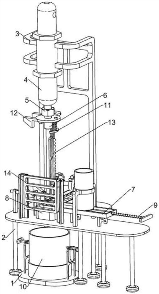
[0045] A punching device for valve spring seats such as figure 1 As shown, it includes a bottom plate 1, a support seat 2, an installation seat 3, a cylinder 4, a push rod 5, a punching module 6, a placement groove plate 7, a pressure block 8, a pushing mechanism 9 and a collection mechanism 10. The top of the bottom plate 1 A collection mechanism 10 is provided, which is provided with a support seat 2, the support seat 2 is located above the bottom plate 1, and the rear side of the top of the support seat 2 is provided with a mounting seat 3, and the upper part of the mounting seat 3 is provided with a cylinder 4, and the telescopic end of the cylinder 4 is connected with a pusher The rod 5, the bottom of the push rod 5 is provided with a punching module 6, the top of the support seat 2 is provided with a placement trough 7, the placement trough 7 is provided with a pushing mechanism 9, and the left side of the top of the support seat 2 is provided with a bearing block 8, The...

Embodiment 2

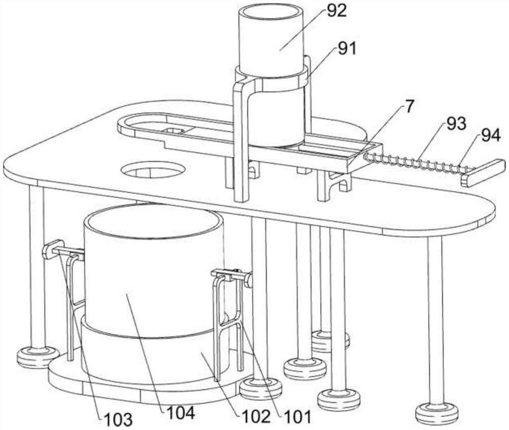
[0048] On the basis of Example 1, such as figure 2 and Figure 6 As shown, the pushing mechanism 9 includes a support frame 91, a placement frame 92, a feeding hand push rod 93 and a first back-moving spring 94, and the sliding type on the right side of the placement slot plate 7 is provided with a feeding hand push rod 93, and the feeding hand A first return spring 94 is connected between the push rod 93 and the right side of the placement slot plate 7 , a support frame 91 is provided on the top of the support seat 2 , and a placement frame 92 is provided on the support frame 91 .

[0049] The staff can put the valve spring seat into the placement frame 92, and manually drive the feeding hand push rod 93 to move to the left to push the bottom valve spring seat to move to the left, and the first return spring 94 is compressed to complete the pushing. Seat moves to corresponding position, stops to promote feeding hand push rod 93, and first back-moving spring 94 resets and dr...

Embodiment 3

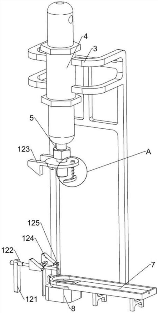
[0053] On the basis of Example 2, such as Figure 3 to Figure 9 As shown, a clamping mechanism 11 is also included. The clamping mechanism 11 includes a connecting rod 111, a clamping block 112 and a first limit spring 113. The right side of the punching module 6 is slidably provided with a connecting rod 111. The connecting rod 111 A clamping block 112 is provided at the bottom, and a first limit spring 113 is connected between the clamping block 112 and the bottom of the punching module 6 .

[0054] The punching module 6 moves downwards through the connecting rod 111 to drive the clamping block 112 to move downwards and contact the valve spring seat, the first limit spring 113 is compressed, and the connecting rod 111 stops moving, so that the valve spring seat in the punching hole can be fixed. Carry out limit, cooperate punching, punching is finished, and punching module 6 moves upwards and drives its upper part to move upwards, and clamping block 112 moves to no longer co...


PUM


Abstract

The invention relates to punching equipment, in particular to punching equipment for a valve spring retainer. Particularly, the invention provides the punching equipment for the valve spring retainer, which has the advantages that manual pushing and fixing are not needed, the safety is guaranteed, waste and finished products are collected separately, and post-treatment is coordinated. The punching equipment for the valve spring retainer comprises a base plate, a supporting base, a mounting base, a placing groove plate and a pressure-bearing block, wherein a collecting mechanism is arranged at the top of the base plate, the supporting base is arranged, the mounting base is arranged on one side of the top of the supporting base, an air cylinder is arranged on the upper portion of the mounting base, the telescopic end of the air cylinder is connected with a pushing rod, a punching module is arranged at the bottom of the pushing rod, the placing groove plate is arranged at the top of the supporting base, a material pushing mechanism is arranged on the placing groove plate, and the pressure-bearing block is arranged on one side of the top of the supporting base. According to the punching equipment, the punching module is driven to move downwards to conduct punching on the valve spring retainer, so that the basic functions of the equipment are achieved.

Description

technical field [0001] The invention relates to a punching device, in particular to a punching device for a valve spring seat. Background technique [0002] The valve spring seat is an important part in the engine valve train. It is usually cylindrical and has two steps. The corresponding steps are processed on the cylindrical blank by cutting or milling, and then punched. [0003] The existing technology needs to manually push and fix the cylindrical blank, and the punching machine punches it, which has great safety hazards, and the waste materials punched out are not easy to collect, which affects the working environment. Therefore, it is necessary to design a manual push and fix , to ensure safety, separate collection of waste materials and finished products, and punching equipment for valve spring seats in conjunction with post-processing. Contents of the invention [0004] In order to make up for the shortcomings of the existing technology that the cylindrical blank...

Claims


Application Information

Patent Timeline
Patent Type & Authority Applications(China)
IPC IPC(8): B21D28/24B21D43/20B21D43/02B21D45/06
CPCB21D28/243B21D43/20B21D43/02B21D45/06B21D45/006
Inventor 黄建民
Owner 江西樟树市福铃内燃机配件有限公司
Why Eureka
Try Eureka