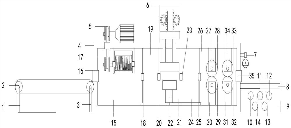
[0003] The technical problem to be solved by the present invention is to overcome the defects of the prior art. The present invention provides a building steel bar straightening device. By turning on the power supply, the entire building steel bar straightening device starts to run, and then press the first button to let the transmission mechanism and The drive mechanism starts running and the first button starts the conveyor mechanism and the drive mechanism which starts the inside of the
rebar straightening unit and puts the
rebar on the
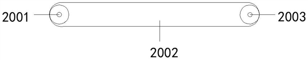
conveyor belt, at which point the fifth and sixth pulleys start rolling , and the rotation of the fifth
pulley and the sixth
pulley will drive the rotation of the
conveyor belt, and the
conveyor belt can allow the steel bars to advance by themselves, so that there is no need for a large number of people to take the steel bars, and the rotation of the conveyor belt will allow the steel bars to enter through the feed port At this time, the motor in the driving mechanism starts to rotate, and the rotation of the motor will drive the rotation of the first transmission shaft, and the rotation of the motor will drive the inside of the transmission box to start running, and the rotation of the first transmission shaft will drive the first The rotation of the first
scroll wheel will simultaneously drive the rotation of the scroll belt, and the rotation of the scroll belt will drive the rotation of the second
scroll wheel, and at the same time the rotation of the second
scroll wheel will drive the rotation of the second rotation shaft, and the second rotation shaft can Provide driving force for the conveying mechanism, so as to ensure that the conveying mechanism can rotate, and the rotation of the second rotating shaft will drive the operation of the conveying mechanism; The function of guiding the direction, and the thread on the surface of the thread rolling cylinder matches the texture on the surface of the steel bar, and the rotation of the thread rolling cylinder will drive the steel bar to move forward, so that the steel bar enters the first straightening box from the first exit At this time, press the second button to start the operation of the first straightening box, and the first straightening box can straighten the steel bars; the operation of the first straightening box will make the straightening box The
hydraulic cylinder starts to stretch toward the middle part of the straightening box, and with the extension of the
hydraulic cylinder, the arc plate will start to stretch, and the four arc plates will form an arc shape, and at the same time, as the steel bar moves forward The operation will pass through the circular arc formed by the four circular arc plates, and the steel bar will straighten the steel bar through the circular arc shape, and it will not deviate quickly inside the steel bar straightening device, so that it can be carried out more effectively. Straightening operation, so as to carry out the first straightening operation on the steel bar, and then the steel bar will enter the fixing box through the second outlet; at this time, pressing the third button will make the fixing mechanism start to run, and the fixing mechanism can perform a straightening operation on the steel bar fixed, so that the steel bar in the heating box can be heated stably, and the operation of the fixing mechanism will make the first gear and the second gear roll down, and the rolling down of the first gear and the second gear will drive The downward movement of the slider, and the rotation of the first gear and the second gear can drive the upward movement or downward movement of the slider and the first connecting block, so as to fix the steel bar, and the downward movement of the slider will drive The downward movement of the first support rod and the second support rod, and the downward movement of the first support rod and the second support rod will drive the downward movement of the first connecting block, thereby performing a fixing operation on the steel bar; When the steel bar is fixed, and the fixing mechanism is at a certain To a certain extent, the steel bar also has a straightening effect. The end of the steel bar will enter the heating box through the third outlet. At this time, press the fourth button to start the operation inside the heating box, and the heating box provides a heating place for the steel bar. At the same time, it provides the necessary conditions for the subsequent straightening operation. At the same time, the steel bar will be in the arc groove on the support plate, and the gas in the gas
bottle will be transported to the
flame nozzle through the
pipe, and the gas will heat the steel bar through the
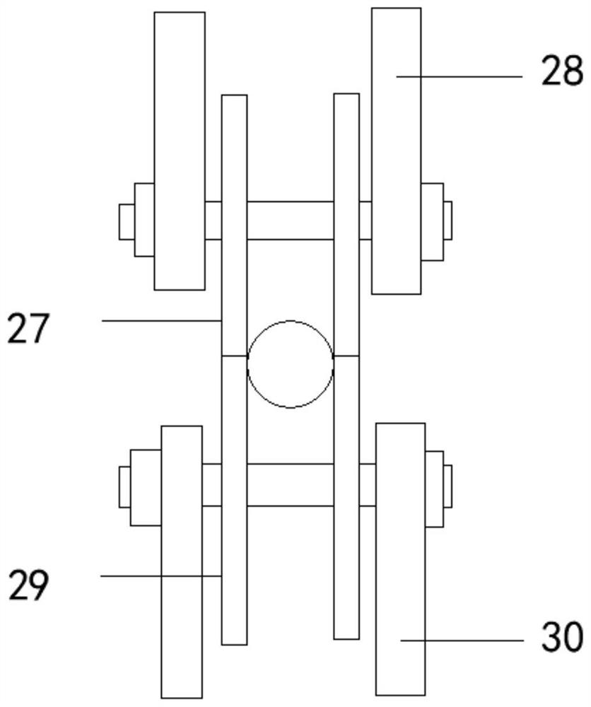
flame nozzle. operation, so that the steel bar is softened, and then the steel bar will enter the second straightening box through the fourth outlet, and the steel bar will be straightened when entering the second straightening box, so that the steel bar that has been straightened once can become straighter ;Press the fifth button to make the second straightening box start to run, and at the same time the first
pulley, the second pulley, the third pulley and the fourth pulley start to rotate, and the fifth button allows the second straightening box to straighten the steel bars , and the steel bar will pass through a circular hole formed by the first pulley and the second pulley, and a circular hole formed by the third pulley and the fourth pulley, thereby performing a second straightening operation on the steel bar, and the rotation of the four pulleys will be Let the steel bar pass through the formed circular hole accurately, so that the steel bar is more straight; the steel bar after the second straightening operation will be transported to the surface of the receiving table through the
discharge port, and the telescopic rod in the cutting mechanism Start to stretch downward, and the cutting blade starts to rotate at a high speed. With the downward stretching of the telescopic rod, the cutting blade will
cut the steel bar. After the steel bar is
cut, the steel bar straightening operation is completed, and the straight steel bar is discharged from the Out of the mouth, the cutting blade in the cutting mechanism will
cut the steel bar, so that the construction personnel will wait for the steel bar of the required length; in the present invention, the first straightening box, the second straightening box, the heating box, the fixing box, the console, The design of the conveying mechanism, driving mechanism and conveying mechanism can make the wound steel bars straight, thus avoiding the collapse of the building and the tilting of the building. security, and the design of the cutting mechanism in the present invention avoids the situation that the straightened steel bar is not easy to carry, and the situation that the steel bar slips will not occur, which solves the problem mentioned in the above background technology. The steel bars shipped from the steel bar factory are wound steel bars, and the wound steel bars are curved, but the steel bars for construction need straight steel bars, and a large amount of steel bars are needed in the construction process, but The current steel bar straightening device cannot make the steel bar completely straight, and in the process of construction, the steel bar is not straight, and the phenomenon of building collapse and building tilting is prone to occur during the construction process. In this case, it is necessary to Re-build, and re-build is time-consuming and costly, and at the same time poses a certain danger to the personal safety of construction workers; and there is no cutting device designed in the existing straightening
machine, so it will cause the straightened steel bar It is not easy to carry, and at the same time, there will be problems of steel bars slipping
