Mold for high-speed punching machine flywheel production

A high-speed punch and flywheel technology, applied in the field of molds for high-speed punch flywheel production, can solve the problems of low processing and molding efficiency, mold damage, and affecting the next use of the mold, so as to improve processing and molding efficiency, increase service life, and increase blowing range effect

Inactive Publication Date: 2021-06-25
嵊州市广图机械制造有限公司
View PDF11 Cites 0 Cited by
  • Summary
  • Abstract
  • Description
  • Claims
  • Application Information

AI Technical Summary

Problems solved by technology

[0002] Nowadays, as people's needs continue to increase, people are producing more and more various metal parts, among which the production of flywheels is one of them. In the production process of flywheels, molds are needed. Traditional flywheel production uses The molding efficiency of the mold is low during the processing and production process, so it is not convenient for people to perform rapid prototyping on the flywheel. The traditional mold does not have a heat dissipation mechanism. After the flywheel is formed, it is not convenient for people to quickly discharge a large amount of heat in the flywheel. It is inconvenient to mold the completed flywheel, which reduces the processing and production efficiency of the flywheel. The mold is generally exposed to the outside after use, which is easy to cause damage to the mold, and there are generally some impurities inside the mold after use. , it is inconvenient for people to quickly clean these impurities, which will affect the next use of the mold

Method used


Image

  • Mold for high-speed punching machine flywheel production
  • Mold for high-speed punching machine flywheel production
  • Mold for high-speed punching machine flywheel production

Examples


Embodiment 1

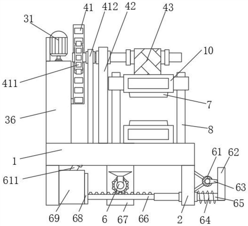
[0029] A mold for high-speed punch flywheel production, such as Figure 1-2 and Figure 5-6As shown, including the placement case 1, the left and right sides of the lower surface of the placement case 1 are fixedly connected with a support plate 2, and one side of the support plate 2 is fixedly connected with a heat dissipation mechanism 6, and the heat dissipation mechanism 6 includes a second motor 61. The left side of the second motor 61 is fixedly connected with the right side of the right support plate 2 through the connecting seat, the output shaft of the second motor 61 is fixedly connected with a cam 63, and the right end of the cam 63 is fitted with a moving plate 62, and the moving plate 62 The first slide bar 65 is fixedly connected to the left side of the left side, and the first slide bar 65 is slidably connected to the first slide sleeve that is clamped on one side of the right support plate 2. The outer surface of the first slide bar 65 is sleeved with A flexib...

Embodiment 2

[0032] A kind of high-speed press flywheel production mold, differs from embodiment 1 in that, as Figure 1-4 As shown, the left side of the upper surface of the support plate 2 is fixedly connected with a moving mechanism 3, the right side of the moving mechanism 3 is fixedly connected with a pressing mechanism 4, and the upper surface of the placement shell 1 is fixedly connected with two second slides. Rod 8, the outer surface of the second sliding rod 8 is provided with a second sliding sleeve, the connection shell 10 is fixedly connected between the two second sliding sleeves and the upper surface of the placement shell 1, and the moving mechanism 3 includes a fixed shell 36 and The first motor 31, wherein, the lower surface of the fixed shell 36 is fixedly connected with the upper surface of the placement shell 1, and the upper surface of the fixed shell 36 is fixedly connected with the left side of the first motor 31 through the fixing seat, and the first motor 31 The o...

Embodiment 3

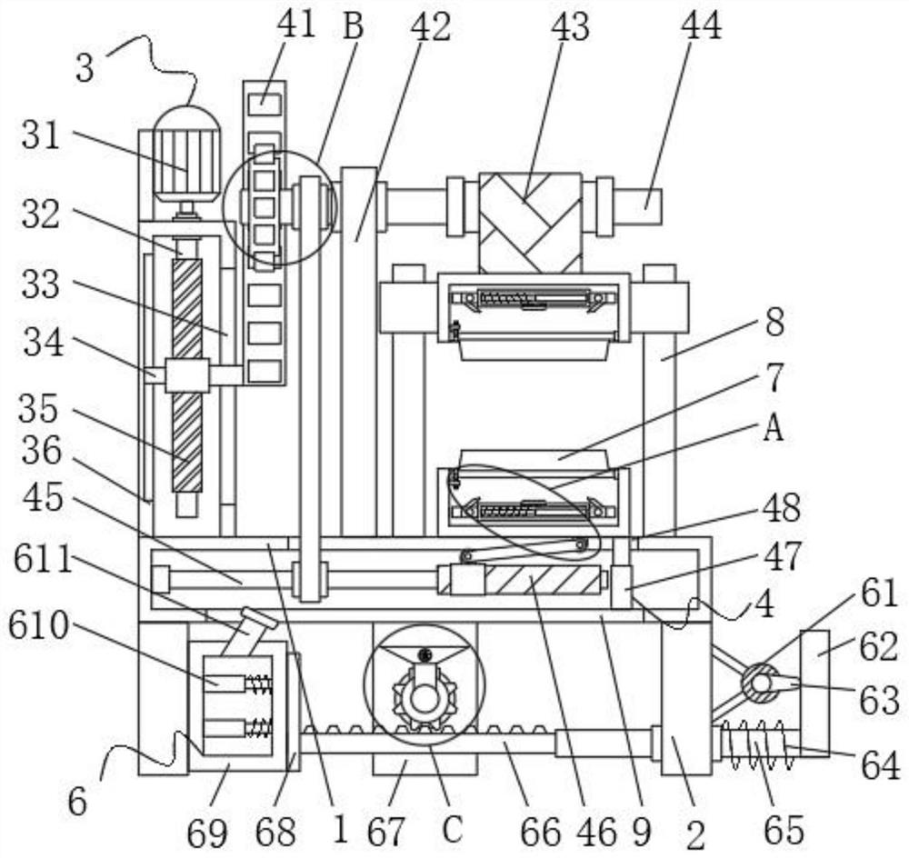
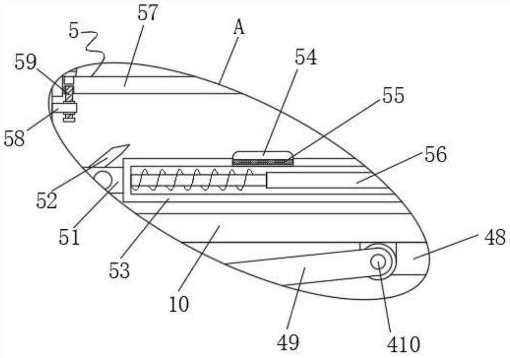
[0035] A kind of high-speed press flywheel production mold, differs from embodiment 1 in that, as Figure 2-3 As shown, the connecting shell 10 is provided with a mold base 7, the connecting shell 10 is provided with a cleaning mechanism 5, the front of the connecting shell 10 is provided with a door, the cleaning mechanism 5 includes a fourth rotating shaft 57, and the fourth rotating shaft 57 The left and right sides of the outer surface are provided with fourth bearings, and the two fourth bearings are respectively clamped on the left and right sides of the inner wall of the connecting shell 10. One side of the fourth rotating shaft 57 is fixedly connected to one side of the mold base 7. The left side of the inner wall of the connecting shell 10 is fixedly connected with a mounting block 58 , and one side of the mounting block 58 is clipped with a second threaded post 59 , and one end of the second threaded post 59 is inserted into the limit position provided on one side of ...


PUM


Abstract

The invention discloses a mold for high-speed punching machine flywheel production, and relates to the technical field of molds. The mold comprises a placement shell, the left and right side surfaces of the lower surface of the placement shell are fixedly connected with supporting plates, and one side surface of each supporting plate is fixedly connected with a heat dissipation mechanism. According to the scheme, by arranging a moving mechanism, a first rotating shaft can drive a reciprocating lead screw to rotate through starting of a first motor, so that a lead screw seat drives a first rack to move up and down. By arranging a pressing mechanism, a second rotating shaft can rotate through meshing of the first rack and a first gear; a transmission belt is loosened, then a heavier second sliding sleeve drives an upper side mold base to move downwards, a first threaded column is rotated, a lower side mold base can move upwards through movement of a connecting rod, and then the two mold bases get close to the middle to press raw materials on the mold bases. Therefore, repeated pressing is carried out, and the machining and forming efficiency of a flywheel in the production process is improved.

Description

technical field [0001] The invention relates to the technical field of molds, in particular to a mold for high-speed punch flywheel production. Background technique [0002] Nowadays, as people's needs continue to increase, people are producing more and more various metal parts, among which the production of flywheels is one of them. In the production process of flywheels, molds are needed. Traditional flywheel production uses The molding efficiency of the mold is low during the processing and production process, so it is not convenient for people to perform rapid prototyping on the flywheel. The traditional mold does not have a heat dissipation mechanism. After the flywheel is formed, it is not convenient for people to quickly discharge a large amount of heat in the flywheel. It is inconvenient to mold the completed flywheel, which reduces the processing and production efficiency of the flywheel. The mold is generally exposed to the outside after use, which is easy to cause...

Claims


Application Information

Patent Timeline
Patent Type & Authority Applications(China)
IPC IPC(8): B22D18/02B22D27/04B08B1/00B08B3/02
CPCB22D18/02B22D27/04B08B1/005B08B1/008B08B3/02
Inventor 叶向阳
Owner 嵊州市广图机械制造有限公司
Why Eureka
Try Eureka