
Lithium battery outer package information printing device for electronic products

A technology for electronic products and printing devices, applied in the field of lithium battery outer packaging information printing devices, can solve the problems of low efficiency, time-consuming and labor-intensive, etc., and achieve the effect of automatic interval blanking

Inactive Publication Date: 2021-06-25
江西腾世优新能源有限公司
View PDF0 Cites 2 Cited by
  • Summary
  • Abstract
  • Description
  • Claims
  • Application Information

AI Technical Summary

Problems solved by technology

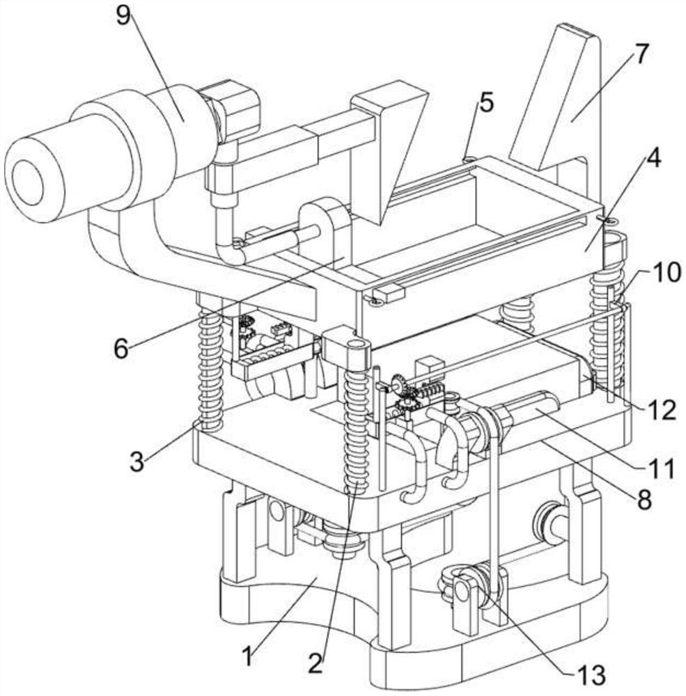
[0004] In order to overcome the shortcomings of manual operation that is not only time-consuming and labor-intensive, but also low in efficiency, the technical problem of the present invention is to provide a lithium battery outer packaging information printing device for electronic products that can realize automatic printing and save time and effort

Method used


Image

  • Lithium battery outer package information printing device for electronic products
  • Lithium battery outer package information printing device for electronic products
  • Lithium battery outer package information printing device for electronic products

Examples


Embodiment 1

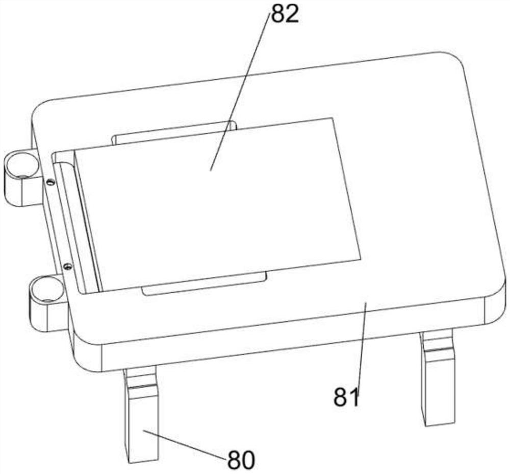
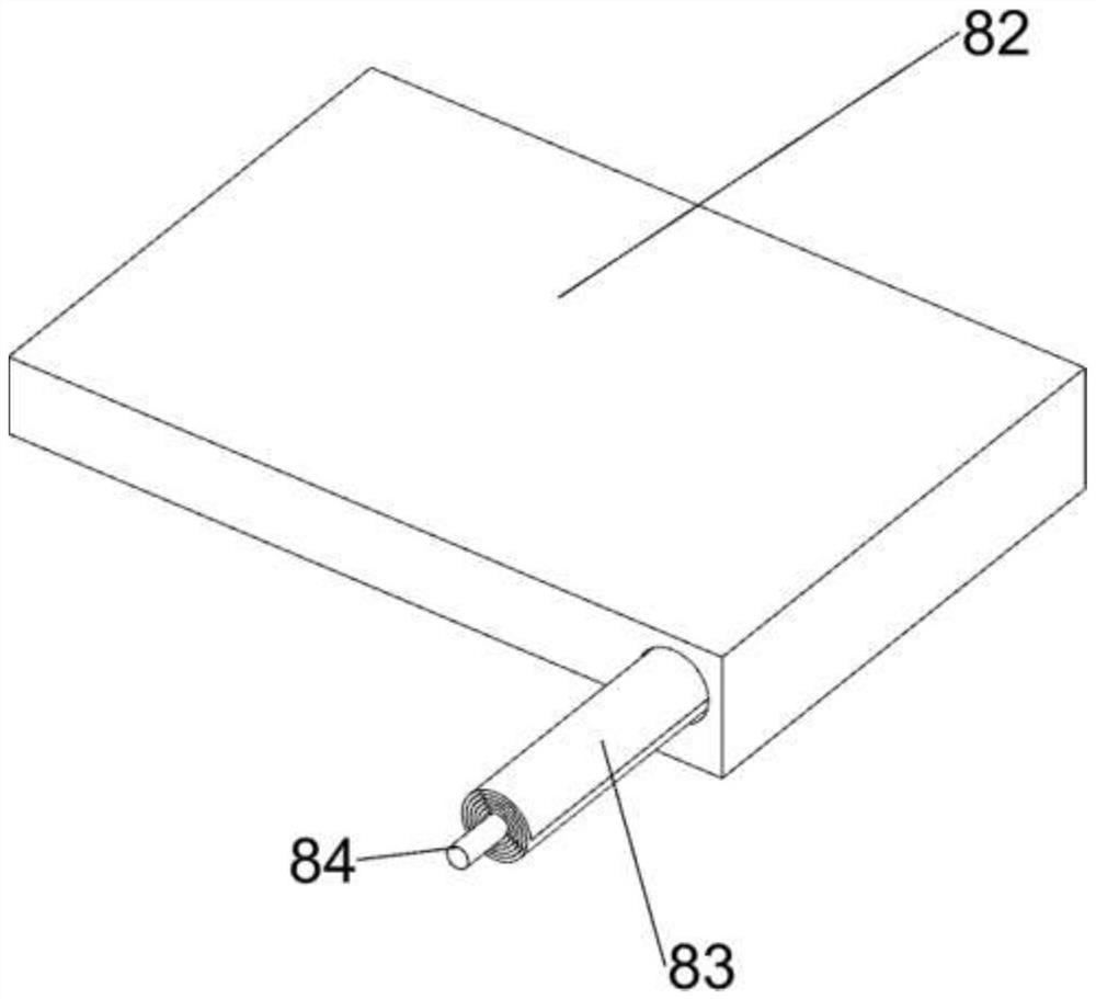
[0027] A lithium battery external packaging information printing device for electronic products, such as Figure 1-5 As shown, including the bottom plate 1, the first guide rod 2, the first spring 3, the printed plate 4, the fixing ring 5, the blade 6, the first wedge block 7, the placement mechanism 8, and the power mechanism 9, and the bottom plate 1 There is a placement mechanism 8, and the first guide rod 2 is provided with a first guide rod 2 between the top of the placed mechanism 8, and the first guide rod 2 has a printed sheet 4, and the bottom four sides and placement mechanism 8 in the printing plate 4 are provided. The first spring 3, the printing plate 4 is slidably connected to the blade 6, and the printing plate 4 is provided with a fixed sleeve 5, and the power mechanism 9 is provided on the left side of the printed plate 4. The first side of the printed plate 4 is provided. Wedge block 7.

[0028] The placement mechanism 8 includes a first support plate 80, a mounti...

Embodiment 2

[0032] On the basis of Example 1, such as Figure 6-9As shown, it is also included, and the sheet mechanism 13 includes a third connecting plate 130, a traction line 131, a third support plate 132, a connecting shaft 133, a wheel 134, a fixing rod 135, a rail 136. The fourth connecting plate 137, the rack 138, and the sixth spring 139 are provided with the third connecting plate 130 on both sides on the right side of the platen 82. Both sides of the bottom plate 1 have two third support plates 132, two A connecting shaft 133, a first support plate 80, a connecting shaft 133, and a first support plate 80 on the right side are connected between the third support plates 132. The front and rear side of the mounting plate 81 and the front and rear side of the bottom plate are rotated. 134. The bottom of the third connecting plate 130 is provided with a traction line 131, and both the front and rear of the mounting plate 81 are provided with two fixed rods 135, and there is a rail 136 be...


PUM


Abstract

The invention relates to a printing device, in particular to a lithium battery outer package information printing device for electronic products. The technical problem of the invention is to provide the lithium battery outer package information printing device for the electronic products, and the lithium battery outer package information printing device can realize automatic printing and is time-saving and labor-saving. The lithium battery outer package information printing device for electronic products comprises a bottom plate, first guide rods, first springs, a printing plate, a placing mechanism and a power mechanism, the placing mechanism is arranged on the bottom plate, the first guide rods are arranged on the four sides of the top of the placing mechanism, and the printing plate is slidably connected between the first guide rods. And through cooperation between the placing mechanism and the power mechanism, the effect of automatically printing the outer package information of the lithium battery can be achieved, traditional manual operation can be replaced, and time and labor are saved.

Description

Technical field [0001] The present invention relates to a printing apparatus, and more particularly to a lithium battery outlet information printing apparatus for electronics. Background technique [0002] With the continuous improvement of economic level, people's quality of life is also growing, and the requirements for electronic products are also increasing, and electronic products will be updated every year. The outer packaging needs to keep up with consumers. [0003] In order to beautify the outer packaging of electronic products, it is necessary to print information and pattern printing on the outer packaging of electronic products. Now printing is manually operated, not only the time is expensive, but it is now able to develop an energy. Automatic printing and saving of lithium battery outsourcing information printing apparatus for electronic products. Inventive content [0004] In order to overcome the manual operation, the technical problem of the present invention is...

Claims


Application Information

Patent Timeline
Patent Type & Authority Applications(China)
IPC IPC(8): B41F17/00B65B61/26
CPCB41F17/00B65B61/26
Inventor 李华平
Owner 江西腾世优新能源有限公司
Learn More