
Automatic grabbing device with self-adaptive grabbing force in fragile product production line

A grabbing device and self-adaptive technology, which is applied in the field of automatic grabbing devices in the fragile product production line, can solve problems such as difficulty in adjusting the force of the claw hook, broken items, and inconvenient loading and unloading, etc., to achieve the effect of high work freedom

Inactive Publication Date: 2021-06-25
义乌市茜朵信息科技有限公司
View PDF3 Cites 0 Cited by
  • Summary
  • Abstract
  • Description
  • Claims
  • Application Information

AI Technical Summary

Problems solved by technology

The new mechanical automatic grabbing device has a simple structure, low manufacturing cost, and is easy to produce, and the gripping range and strength of the gripper are controlled by the telescopic rod, which is convenient for grabbing parts of different sizes and ensures the gripping force enough, there will be no problem of insecure grasping”, but the device does not have the function of easy loading and unloading, and the degree of freedom of the device is not high enough;
[0005] 2. The comparative document CN111285097A (2020-03-02) discloses a mechanical automatic grabbing device, "including a fixed frame, a fixed plate, a second pulley, a grabbing head and an angle adjustment mechanism. An angle adjustment mechanism is set, and the cylinder is extended forward, thereby driving the swing seat at the upper end of the fixed head to swing inside the bearing seat, so that the fixed shaft at the upper end of the swing seat drives the angle of the grab head to change, achieving the ability to quickly adjust the grab The advantages of the inclination angle of the head are taken; by setting the buffer mechanism at the upper end of the angle adjustment mechanism, when the swing seat is pressed down, the pressure block will be pressed to move to the inside of the installation frame, so that the pressure block presses the pressure spring at the upper end of the telescopic rod to generate Deformation and contraction, so as to slide the swing seat, and achieve the advantage of making the swing seat press down smoothly", but the force of the claw hook is difficult to adjust during the installation process of the device, and it is easy to break the item when grabbing a brittle item ;
[0006] 3. The comparative document CN111673782A (2020-06-12) discloses a mechanical automatic grabbing device, "including a mounting rod, a fixed clamp arm, a movable clamp arm, a fixed suction cup, a dynamic suction cup, a motor frame, a drive motor, a screw, a nut Seat and polished rod, the present invention drives the motor to rotate by starting, the screw rotates, and the nut seat is tightened, so that the fixed clamp arm and the movable clamp arm clamp the smooth sheet, the movable suction cup and the fixed suction cup play an anti-slip effect, and further, the fixed clamp arm and the fixed clamp arm play an anti-slip effect, and further, the fixed clamp arm and the fixed clamp arm play an anti-slip effect, and further, through the telescopic The cylinder sticks the movable suction cup on the smooth sheet, starts the vacuum pump to suck the movable suction cup on the smooth sheet, and retracts the telescopic cylinder to move the smooth sheet between the fixed clamp arm and the movable clamp arm. Then control the vacuum pump to release the pressure, loosen the smooth sheet, and then place the smooth sheet between the fixed clamp arm and the movable clamp arm, which is convenient to clamp and has the value of popularization and application", but the device has no clamping objects The protection function makes the clipping object easy to fall and damage when clipping and moving

Method used


Image

  • Automatic grabbing device with self-adaptive grabbing force in fragile product production line
  • Automatic grabbing device with self-adaptive grabbing force in fragile product production line
  • Automatic grabbing device with self-adaptive grabbing force in fragile product production line

Examples


Embodiment Construction

[0043] The following will clearly and completely describe the technical solutions in the embodiments of the present invention with reference to the accompanying drawings in the embodiments of the present invention. Obviously, the described embodiments are only some, not all, embodiments of the present invention. Based on the embodiments of the present invention, all other embodiments obtained by persons of ordinary skill in the art without making creative efforts belong to the protection scope of the present invention.

[0044] In the description of the present invention, it should be noted that the terms "upper", "lower", "inner", "outer", "front end", "rear end", "both ends", "one end", "another end" The orientation or positional relationship indicated by etc. is based on the orientation or positional relationship shown in the drawings, and is only for the convenience of describing the present invention and simplifying the description, rather than indicating or implying that ...


PUM


Abstract

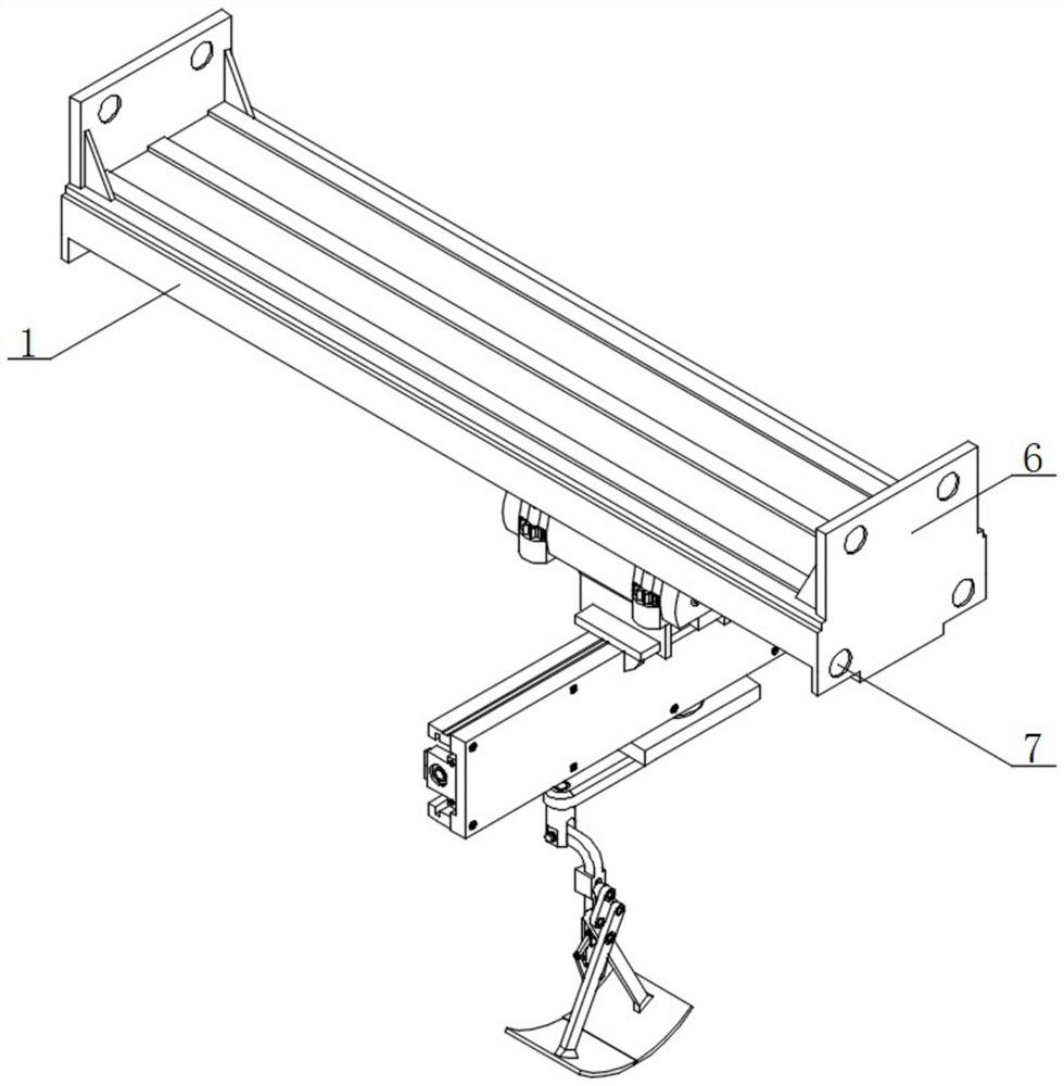
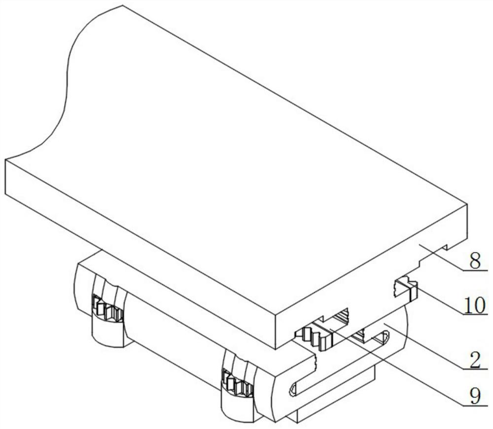
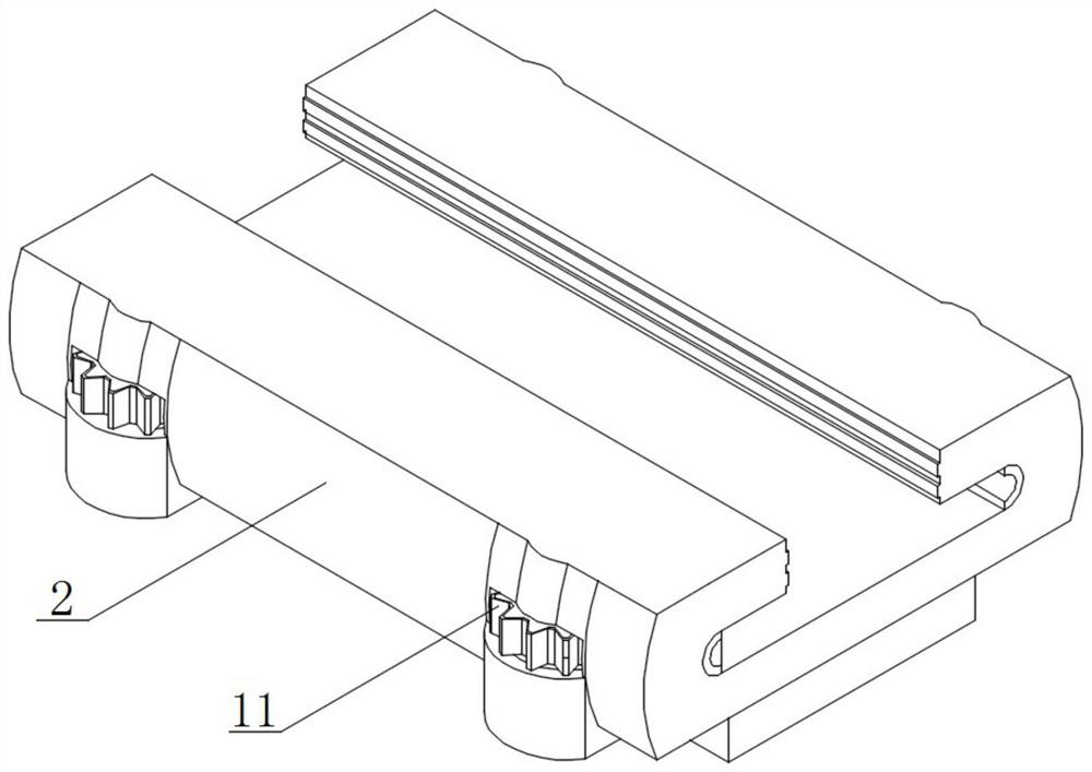
The invention relates to an automatic grabbing device with self-adaptive grabbing force in a fragile product production line. The automatic grabbing device comprises a bearing keel, a positioning sliding block, a limiting threaded rod, an extension spring and a first arc-shaped plate, one side of the bearing keel is fixedly connected with a fixing steel plate, and a fixing hole is formed in the middle of the fixing steel plate; and a supporting plate is fixedly connected to the bottom of the bearing keel, a limiting groove is formed in one side of the supporting plate, the positioning sliding block is slidably connected into the limiting groove, the positioning sliding block is slidably connected to the bottom of the supporting plate through the limiting groove, and positioning clamping teeth are arranged on one side of the bottom of the supporting plate. Through the arrangement of the bearing keel and the positioning sliding block, one side of the bearing keel is fixedly connected with the fixing steel plate, the fixing hole is formed in the middle of the fixing steel plate, and when the device works on the production line, the bearing keel is fixed to a grabbing point of the production line through the fixing steel plate, and the device is easier and more convenient to assemble and disassemble when used.

Description

technical field [0001] The invention relates to the technical field of automatic grabbing, in particular to an automatic grabbing device in a fragile product production line with self-adaptive grabbing force. Background technique [0002] Mechanical automation is the process in which machines or devices are automatically controlled mechanically without human intervention. In recent years, in industrial and other automated production processes, automatic grabbing devices are needed in many places, and are realized through automated control systems. Automatic grabbing can truly achieve large-scale industrial production, reduce labor intensity, and improve labor efficiency. [0003] The existing deficiencies are: [0004] 1. The comparative document CN108483226A (2018-04-14) discloses a new type of mechanical automatic grabbing device, "comprising a bottom plate, a casing and a box, a connecting block is arranged in the middle of the upper surface of the bottom plate, and the ...

Claims


Application Information

Patent Timeline
Patent Type & Authority Applications(China)
IPC IPC(8): B65G47/90
CPCB65G47/90
Inventor 朱红军
Owner 义乌市茜朵信息科技有限公司
Learn More