
A hydraulic synchronous control mechanism with compensation

A control mechanism and hydraulic synchronization technology, applied in mechanical equipment, fluid pressure actuating devices, servo motors, etc., can solve the problems of high maintenance cost, high system oil cleanliness, complex hydraulic and electrical control methods, etc. The effect of high reliability, high synchronization accuracy and simple electrical control method

Inactive Publication Date: 2016-04-13
CHINA NAT HEAVY MACHINERY RES INSTCO
View PDF9 Cites 0 Cited by
  • Summary
  • Abstract
  • Description
  • Claims
  • Application Information

AI Technical Summary

Problems solved by technology

[0005] 3. Each hydraulic cylinder is designed to be controlled by a synchronous motor. The control accuracy is high, but the cumulative error will occur during the synchronous movement of the cylinder. The error can only be eliminated by the hydraulic device of the synchronous motor after the cylinder runs to the limit position. ;
[0006] 4. Each hydraulic cylinder is designed to be controlled by a proportional valve or a servo valve. The control accuracy is extremely high, but the cleanliness of the system oil is required, the hydraulic and electrical control methods are complicated, and the later maintenance costs are relatively high.

Method used


Image

  • A hydraulic synchronous control mechanism with compensation

Examples


Embodiment Construction

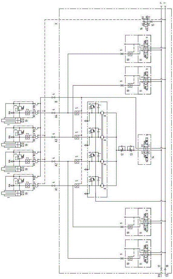
[0022] The invention relates to a novel hydraulic synchronous control mechanism with compensation in the field of hydraulic technology, in particular to a novel hydraulic synchronous control mechanism for synchronizing multiple hydraulic cylinders.

[0023] see figure 1 , the specific structure of a hydraulic synchronous control mechanism with compensation involved in the present invention is:

[0024] Including the main working circuit and compensation circuit; among them,

[0025] The main working circuit includes an oil cylinder 1 provided with a first hydraulic control check valve 2, a first relief valve 3 and a displacement sensor 19, and the oil inlet A3 of the first hydraulic control check valve 2 passes through the first ball valve 4 in sequence , the control of the second hydraulic control check valve 5, the second relief valve 6, the first check valve 7, the synchronous motor 8, the second throttle valve 12, the third throttle valve 13 and the electro-hydraulic reve...


PUM


Abstract

The invention relates to a hydraulic synchronous control mechanism with a compensation function. The hydraulic synchronous control mechanism with the compensation function is characterized by comprising a main operating loop and a compensation loop; the main operating loop comprises an oil cylinder, the oil cylinder is provided with a first hydraulic control one-way valve, a first overflow valve and a displacement sensor, and an oil inlet of the first hydraulic control one-way valve is connected with an oil opening of a control cavity of an electro-hydraulic reversing valve after sequentially passing through a first ball valve, a second hydraulic control one-way valve, a second overflow valve, a first one-way valve, a synchronous motor, a second throttling valve and a third throttling valve; the compensation loop is arranged between the first ball valve and the second hydraulic control one-way valve and comprises a first throttling valve, a third hydraulic control one-way valve and a first electromagnetic reversing valve, and the first throttling valve, the third hydraulic control one-way valve and the first electromagnetic reversing valve are sequentially connected. The hydraulic synchronous control mechanism with the compensation function which is disclosed by the invention has the characteristics that the structure is simple, the position of the oil cylinder is accurate, the synchronization precision is high, an electric control manner is simple, the use reliability is high, the safety of a system is remarkable, the maintenance is convenient and the like.

Description

technical field [0001] The invention relates to a hydraulic synchronous control mechanism with compensation. Background technique [0002] At present, multiple hydraulic cylinder synchronous control devices in the field of hydraulic technology at home and abroad mainly include the following control methods: [0003] 1. Each hydraulic cylinder is designed with a throttle valve for control, the control accuracy is low, and the synchronization accuracy is affected by the load of the cylinder and the oil temperature; [0004] 2. Each hydraulic cylinder is designed with a speed regulating valve for control. The control accuracy is general, and the synchronization accuracy is less affected by the load of the oil cylinder and the oil temperature; [0005] 3. Each hydraulic cylinder is designed to be controlled by a synchronous motor. The control accuracy is high, but the cumulative error will occur during the synchronous movement of the cylinder. The error can only be eliminated b...

Claims


Application Information

Patent Timeline
Patent Type & Authority Patents(China)
IPC IPC(8): F15B11/16F15B11/22
Inventor 郭星良丘铭军艾春璇
Owner CHINA NAT HEAVY MACHINERY RES INSTCO
Learn More