Positioning claw cutting feeding device

A technology of feeding device and positioning claw, which is applied in the direction of conveyor objects, transportation and packaging, assembly/disassembly of contact parts, etc., and can solve the problems of unable to meet the assembly requirements of positioning claws and slow speed

Pending Publication Date: 2021-06-25
昆山市德来福工业自动化有限公司
View PDF4 Cites 0 Cited by
  • Summary
  • Abstract
  • Description
  • Claims
  • Application Information

AI Technical Summary

Problems solved by technology

The base of the electrical connector is equipped with several positioning claws for adapting electric needles. In the past, these positioning claws were manually assembled one by one, and the speed was relatively slow.
With the miniaturization of electrical connectors and the diversification of functions, the diameter of positioning claws gradually decreases, and the density of positioning claws gradually increases. Manual assembly can no longer meet the assembly requirements of positioning claws in existing electrical connectors, so automation Equipment for assembling positioning claws is born on demand

Method used


Image

  • Positioning claw cutting feeding device
  • Positioning claw cutting feeding device
  • Positioning claw cutting feeding device

Examples


Embodiment

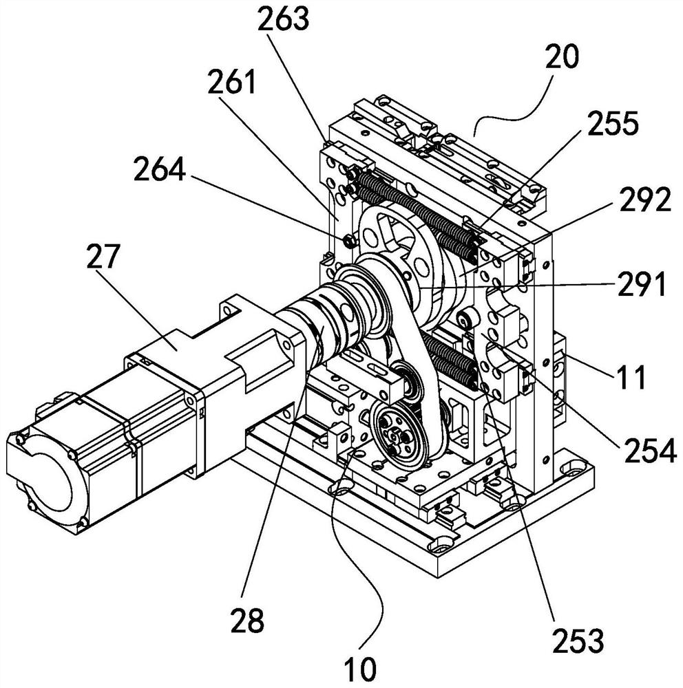
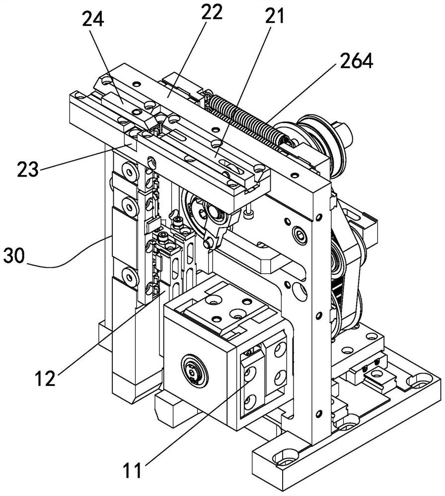
[0019] A positioning claw cutting and feeding device, comprising a material belt lifting mechanism 10, a material head side pushing cutting mechanism 20 and a material belt guiding mechanism 30, the material head side pushing and cutting mechanism 20 is located above the material belt guiding mechanism 30, and the material belt The guiding mechanism 30 is located beside the strip guiding mechanism 30 . The material head side pushing and cutting mechanism 20 includes a side pushing block 21, a guide block 22, a lining block 23, a limit block 24, a power transmission component 1 25, a power transmission component 2 26 and a servo reduction motor 27, and the guide block 22 is arranged horizontally. The lining block 23 is fixed in the guide block 22, the side pushing block 21 and the limiting block 24 are slidably connected in the guiding block 22, and are respectively located on both sides of the lining block 23, and the side pushing block 21 is arranged on one side corresponding ...


PUM


Abstract

The invention provides a positioning claw cutting feeding device. The device comprises a material belt lifting mechanism, a material head side pushing and cutting mechanism and a material belt guiding mechanism, the material head side pushing and cutting mechanism is located above the material belt guiding mechanism, and the material belt guiding mechanism is located beside the material belt guiding mechanism. The material head side pushing and cutting mechanism firstly bends a material head which shields positioning claws in the side direction, after the highest positioning claw is taken away, the material head side pushing and cutting mechanism removes redundant material heads, the material belt guiding mechanism and a material belt lifting mechanism cooperate to achieve automatic ascending and feeding of a material belt, a new material head and the new positioning claws are conveyed to the grabbing height, and the synergistic effect of the three mechanisms ensures that a positioning claw mounting mechanism can smoothly take away the positioning claws from the specified height.

Description

technical field [0001] The invention relates to the technical field of electrical connector assembly, in particular to a positioning claw cutting and feeding device. Background technique [0002] With the continuous development of science and technology, electrical connectors are used in a large amount and in a wide range, but for a long time, people have not paid enough attention to them, and the connection process of electrical connectors is often ignored in the production process. Due to the fault problem caused by the connection of the electrical connector, it has a great impact on the aircraft, so we must pay attention to the process of connecting the electrical connector. The base of the electrical connector is equipped with several positioning claws for adapting the electric needles. In the past, these positioning claws were manually assembled one by one, and the speed was relatively slow. With the miniaturization of electrical connectors and the diversification of f...

Claims


Application Information

Patent Timeline
Patent Type & Authority Applications(China)
IPC IPC(8): B65G47/90B65G47/74H01R43/20
CPCB65G47/90B65G47/74H01R43/20
Inventor 朱中涛曹家楼张春露王业昌刘星
Owner 昆山市德来福工业自动化有限公司
Why Eureka
Try Eureka