
Automatic tissue rolling mechanism and wet tissue machine
An automatic technology for roll towels, applied in the direction of winding strips, thin material processing, household appliances, etc., can solve the problem of limited length range of wet wipes
- Summary
- Abstract
- Description
- Claims
- Application Information
AI Technical Summary
Problems solved by technology
Method used
Image

Examples
Embodiment Construction
[0032] The present invention will be further described below with reference to the accompanying drawings.
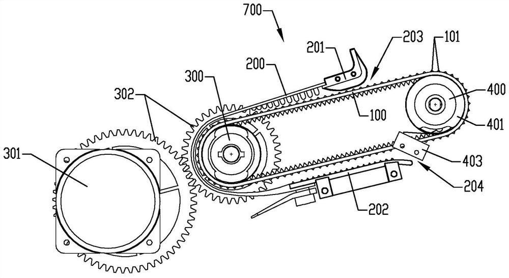
[0033] Such as figure 1 , Figure 4-5 As shown, the automatic roll mechanism includes a inner track 100, an outer track 200, a drive shaft 300, a driven shaft 400, and a power.
[0034] The driving force is composed of the motor 301 and the gear 302, one of which is fitted at one end of the drive shaft 300, and the motor rotates to rotate with the drive shaft by the gear drive.
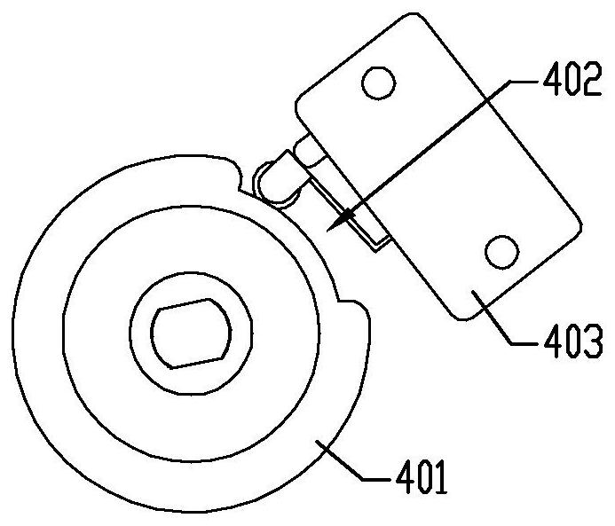
[0035] The drive shaft 300, the driven shaft 400 is parallel, and both ends are rotated on the left side plate 501, the right side plate 502. The left end of the driven shaft is configured with a concave cam 401 that has a gap 402 of the peripheral surface of the concave cam. In order to alleviate the drive shaft, the weight of the driven shaft itself is made into hollow, non-solid structure.
[0036] The inner track 100 is ring-shaped and is sleeved on the drive shaft 300 and the driven shaft 400, t...
PUM
 Abstract
Description
Claims
Application Information