Cutting and spinning synergetic fatigue low-stress blanking device and method

A low stress and fatigue technology, applied in the direction of manufacturing tools, other manufacturing equipment/tools, etc., can solve the problems of inability to smoothly transition, poor cutting section quality, large shear force, etc. Diameter ratio range, the effect of prolonging the service life

Active Publication Date: 2022-05-20
CHINA UNIV OF PETROLEUM (EAST CHINA)
View PDF5 Cites 0 Cited by
  • Summary
  • Abstract
  • Description
  • Claims
  • Application Information

AI Technical Summary

Problems solved by technology

[0003]Most of the existing low-stress blanking methods require pre-manufactured V-shaped grooves, the process is cumbersome, and the shear force required for grooves is relatively large. For large-diameter bars When blanking, the equipment needs a large total power, which requires high equipment, and can only blank a specific length of bar. The crack initiation force required by the bar and the expansion force after crack initiation are quite different, which cannot be stable. The transition, loading force and crack propagation direction are not easy to control, resulting in poor quality of blanking section and other problems

Method used


Image

  • Cutting and spinning synergetic fatigue low-stress blanking device and method
  • Cutting and spinning synergetic fatigue low-stress blanking device and method
  • Cutting and spinning synergetic fatigue low-stress blanking device and method

Examples


Embodiment 1

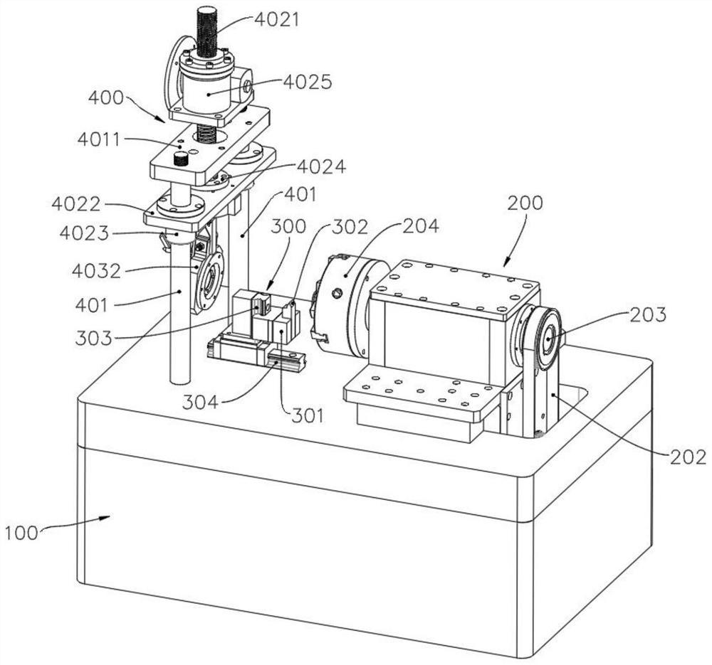
[0041] Refer to attached Figure 1-6 As shown, the present invention provides a technical solution: a cutting and bending cooperative fatigue low-stress blanking device, including a frame 100, a clamping and rotating mechanism 200, a cutting mechanism 300 and a loading mechanism 400, a clamping and rotating mechanism 200, Both the cutting mechanism 300 and the loading mechanism 400 are installed on the frame 100, the clamping and rotating mechanism 200 and the loading mechanism 400 are respectively arranged on the left and right sides of the cutting mechanism 300, and the frame 100 provides base support for the device;

[0042] Wherein, the clamping and rotating mechanism 200 includes a servo motor 201, a main shaft 203 and a three-jaw chuck 204, the servo motor 201 is fixedly installed on the bottom of the frame 100, the main shaft 203 and the three-jaw chuck 204 are arranged on the top of the frame 100, three The jaw chuck 204 is fixedly connected to one end of the main shaf...

Embodiment 2

[0054] Refer to attached Figure 7 As shown, the embodiments of the present invention also provide a cutting and bending cooperative fatigue low-stress blanking method, which includes the following steps:

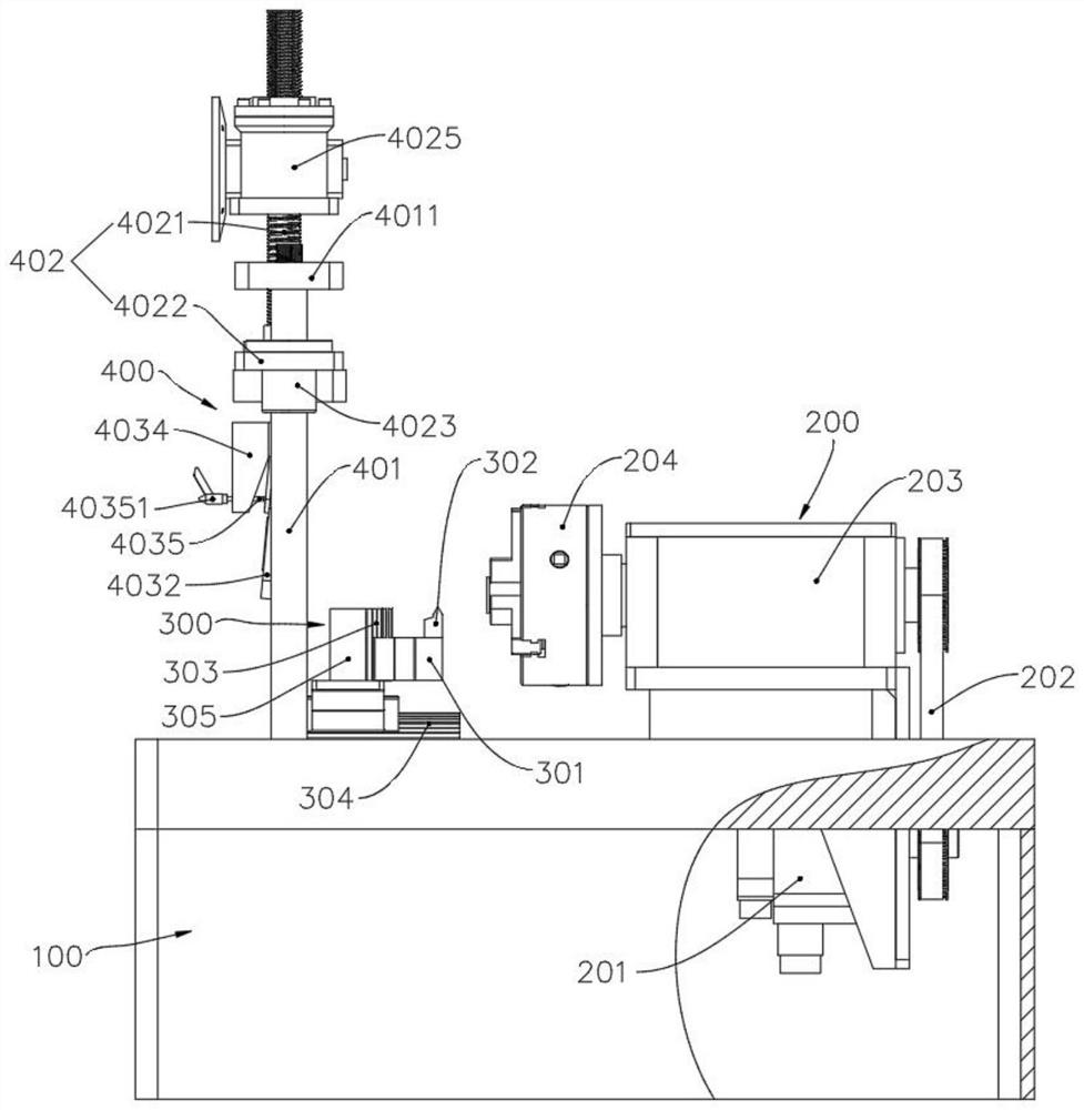
[0055] S1, install the bar material, pass the bar material to be unloaded through the center of the follower bearing 4036, and extend it into the inside of the three-jaw chuck 204 for clamping and fixing, turn on the servo motor 201, and output power to the main shaft through the timing belt 202 203, the main shaft 203 drives the bar held by the three-jaw chuck 204 to rotate;

[0056] S2, preset loading force, observe and fine-tune the matching angle between the loading frame 4032 and the connector 4031 through the angle pointer 40322, then tighten the quick-release locking part 40351 to fix the angle, and then drive the threaded rod 4021 to move upward through the elevator 4025, and the movable plate 4022 moves upward synchronously under the cooperation of guide bearing 4...


PUM


Abstract

The invention provides a cutting and spinning synergistic fatigue low-stress blanking device and method, and belongs to the technical field of precision forming machining.The device comprises a rack, a clamping rotating mechanism, a cutting mechanism and a loading mechanism, and the clamping rotating mechanism, the cutting mechanism and the loading mechanism are all installed on the rack; the clamping mechanism comprises a servo motor, a main shaft and a three-jaw chuck, the cutting mechanism comprises a tool rest, a cutting tool, a vertical sliding rail, a horizontal sliding rail and a connecting piece, the vertical sliding rail is arranged above the horizontal sliding rail, the cutting tool is fixedly installed on one side of the tool rest, the loading mechanism comprises guide columns, a follow-up assembly and a loading mold, and the guide columns are symmetrically distributed along the central axis of the main shaft; the follow-up assembly comprises a threaded rod and a movable plate, the loading mold comprises a connector, a loading frame and an angle adjusting block, the loading frame is arranged below the connector, the angle adjusting block is arranged on one side of the loading frame and fixedly connected with the connector, and the method comprises the steps of bar mounting, loading force presetting, bar cutting and loading force adjusting.

Description

technical field [0001] The invention belongs to the technical field of precision forming, and in particular relates to a cutting and bending cooperative fatigue low-stress blanking device and method. Background technique [0002] Low-stress blanking is to apply crack technology to bar blanking. First, a circumferential crack is artificially prefabricated on the surface of the bar, and then a certain external force is applied to the bar with a circumferential surface crack. Cracks propagate perpendicular to the axis at specific locations, causing the bars to dynamically separate in the form of low-stress brittle fracture. At present, scholars have conducted some research on low-stress blanking technology from the aspects of stress concentration, mechanism design, and fracture morphology. However, key core technologies such as the material separation mechanism of low-stress blanking, high-efficiency and precise realization methods, and quality evaluation standards have not ye...

Claims


Application Information

Patent Timeline
IPC IPC(8): B23P23/00
CPCB23P23/00
Inventor 张立军徐嘉怡孙旭东周强赵青张强傅术林杨博涵杨宁金泽林王豪马子轩
Owner CHINA UNIV OF PETROLEUM (EAST CHINA)
Why Eureka
Try Eureka