Cast-in-place pile integrity detection device and method based on densely distributed fiber grating temperature sensing technology

A distributed optical fiber and integrity detection technology, which is applied in infrastructure testing, infrastructure engineering, construction, etc., can solve the problem of low accuracy of small-scale defect detection, the inability to guarantee the survival rate of sensors, and prolong the detection time of pile foundations and other problems to achieve the effect of reducing the interference of pile foundation detection, overcoming inaccurate judgments, and reducing measurement costs

Active Publication Date: 2021-06-25
NANJING UNIV
View PDF6 Cites 0 Cited by
  • Summary
  • Abstract
  • Description
  • Claims
  • Application Information

AI Technical Summary

Problems solved by technology

However, the existing traditional temperature measurement methods need to deploy a large number of temperature sensors, which increases the cost of pile foundation detection and cannot guarantee the survival rate of the sensors; while the existing thermal method based on distributed optical fiber temperature measurement technology (DTS) The body integrity detection technology is limited by the spatial resolution and temperature measurement accuracy of the distributed optical fiber temperature measurement technology (DTS), and the detection accuracy for small-scale defects is low, especially for low-quality concrete and short pile lengths. Pouring pile detection accuracy is low
Another method is the pile body integrity detection technology based on the active heating distributed optical fiber temperature measurement technology (DTS), which also judges the integrity of the pile foundation based on the heat conduction characteristics of the pile body, but this method requires Sensing optical fiber heating in cast-in-situ piles is used to detect pile foundation defects, which is complicated to operate and prolongs the time of pile foundation detection

Method used


Image

  • Cast-in-place pile integrity detection device and method based on densely distributed fiber grating temperature sensing technology
  • Cast-in-place pile integrity detection device and method based on densely distributed fiber grating temperature sensing technology
  • Cast-in-place pile integrity detection device and method based on densely distributed fiber grating temperature sensing technology

Examples


Embodiment 1

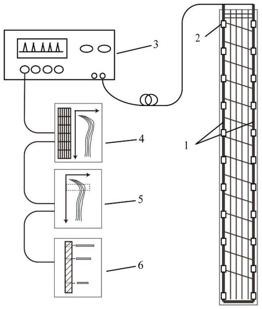
[0063] Such as figure 1 As shown, the integrity detection device and method for cast-in-situ piles based on densely distributed fiber Bragg grating temperature sensing technology includes: armored densely distributed fiber Bragg grating temperature sensing optical fiber 1, temperature sensitization unit 2, and densely distributed temperature demodulator 3. Temperature data processing unit 4, defect analysis unit 5 and pile foundation integrity evaluation unit 6;

[0064] A device and method for detecting the integrity of cast-in-situ piles based on densely distributed fiber grating temperature sensing technology, comprising the following steps:

[0065] Step one, such as figure 2 As shown in Fig. 1, the protective outer layer of the armored dense distributed fiber Bragg grating temperature sensing fiber was peeled off at a certain distance, and the temperature-sensitizing element was adhered to the armored dense distributed fiber Bragg grating temperature sensing fiber ring ...

Embodiment 2

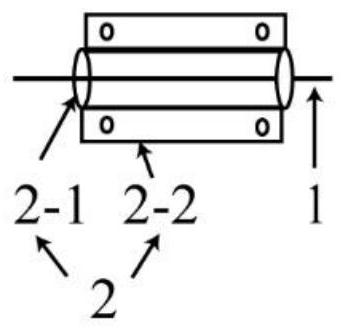
[0073] A device and method for detecting the integrity of cast-in-situ piles based on densely distributed fiber Bragg grating temperature sensing technology, which is characterized in that it includes: armored densely distributed fiber Bragg grating temperature sensing optical fiber 1, temperature-sensitizing unit 2, densely distributed temperature Demodulator 3, temperature data processing unit 4, defect analysis unit 5 and pile foundation integrity evaluation unit 6; It consists of a temperature-sensitizing element 2-1 and a metal protective layer 2-2; the armored densely distributed optical fiber grating temperature sensing optical fiber 1 is fixedly bound on the main reinforcement of the steel cage; the armored densely distributed optical fiber grating temperature sensing optical fiber 1 Connect with the densely distributed temperature demodulator 3; the densely distributed temperature demodulator 3 collects temperature data and transmits it to the temperature data processi...


PUM

PropertyMeasurementUnit
diameteraaaaaaaaaa

Abstract

The invention discloses a cast-in-place pile integrity detection device and method based on a densely distributed fiber grating temperature sensing technology. A metal material with a large thermal expansion coefficient is adopted as a temperature sensitization element, the temperature sensitization element is annularly pasted to the position, without a protective layer, of an optical fiber, and the optical fiber is bound to a main rib of a reinforcement cage in a fixed-point manner; after the reinforcement cage is put down, the optical fiber is connected with a densely distributed temperature demodulator; concrete starts to be poured, and the mass and the use amount of the concrete are recorded; the monitoring time of the temperature of a pile body is determined according to the use amount and the mass of the concrete; after pouring of the concrete of the pile body is completed, the densely distributed temperature demodulator immediately starts to collect temperature data; and the difference of hydration heat of the concrete along the pile body is obtained according to the collected temperature data, whether concrete pouring is uniform or not and the pile diameter range are judged, and the integrity of a cast-in-place pile is further obtained. By means of the cast-in-place pile integrity detection device and method, the temperature measuring precision and the positioning precision are greatly improved, active heating is not needed, and pile foundation defects can be found as soon as possible and repaired in time.

Description

technical field [0001] The invention discloses a device and method for detecting the integrity of cast-in-situ piles based on densely distributed optical fiber grating temperature sensing technology, and relates to the technical field of quality detection of cast-in-situ piles. Background technique [0002] Cast-in-situ piles have large bearing capacity and strong adaptability, and are widely used in most high-rise buildings, bridges and other projects in my country. With the rapid development of infrastructure projects, the demand for cast-in-situ piles will inevitably develop in the direction of larger and deeper. However, affected by factors such as the uncertainty of geological conditions and the complexity of the construction process, the possibility of integrity defects (defects such as broken piles, diameter shrinkage, segregation, and mud inclusions) will appear during the formation of cast-in-situ piles. As high as 15% to 20%. Due to the large depth and high conce...

Claims


Application Information

Patent Timeline
Patent Type & Authority Applications(China)
IPC IPC(8): E02D33/00
CPCE02D33/00
Inventor 王静朱鸿鹄梅国雄刘拯源郑兴韦超高磊施斌
Owner NANJING UNIV
Why Eureka
Try Eureka