Transfer mechanism, blade root transferring trolley, blade tip transferring trolley and blade transfer system

A car body and load-bearing structure technology, which is applied in the direction of wind engine transportation, wind power generation, etc., can solve the problems of difficult blade transfer, blade loss, trolley skidding, etc., and achieve the effect of ensuring the stability of transportation, reducing loss, and ensuring levelness

Active Publication Date: 2021-06-25
SINOMATECH WIND POWER BLADE +1
View PDF19 Cites 0 Cited by
  • Summary
  • Abstract
  • Description
  • Claims
  • Application Information

AI Technical Summary

Problems solved by technology

[0004] Therefore, the technical problem to be solved by the present invention is that during the transportation of the blades in the prior art, due to the uneven transportation road surface, it is difficult to transfer the blades, and the trolley is easy to cause slippage, which in turn causes the car body itself to cause a hard impact, resulting in poor passability. become worse, and the hard impact will also cause wear to the contact surface of the blade, and even cause the blade to slip off the conveying trolley, resulting in the problem of blade loss

Method used


Image

  • Transfer mechanism, blade root transferring trolley, blade tip transferring trolley and blade transfer system
  • Transfer mechanism, blade root transferring trolley, blade tip transferring trolley and blade transfer system
  • Transfer mechanism, blade root transferring trolley, blade tip transferring trolley and blade transfer system

Examples


Embodiment 1

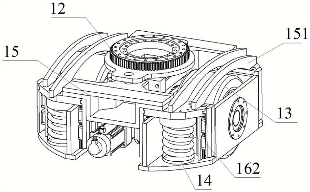
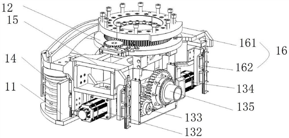
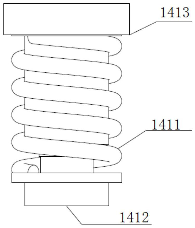
[0108] This embodiment provides a transfer mechanism, such as Figure 1 to Figure 10 As shown, it includes: a transfer base frame 11 ; a load bearing structure 12 , a roller assembly 13 , a buffer assembly 14 and a swing bridge assembly 15 . Wherein, the carrying structure 12 has a mounting portion 122 disposed toward one side of the rotating base frame; the roller assembly 13 includes: a roller member 131 and a roller driver 132, and the roller driver 132 is installed on the transfer base frame 11 Above, the roller member 131 is driven by the roller driver 132 to rotate relative to the transfer base frame 11; the buffer assembly 14 has at least one biasing member, and one end of the biasing member is installed on the transfer base frame 11; the swing bridge assembly 15 and the installation part 122 are pivotally rotated; the swing arm 1512 assembly has a swing structure 151, and the swing structure 151 and the biasing member are opposite to the other side of the transfer base...

Embodiment 2

[0125] This embodiment provides a blade root transfer trolley 2, such as Figure 11 to Figure 13As shown, it includes the transfer mechanism in Embodiment 1, the first car body bracket 21 and the first carrier plate 22 . Wherein, the bearing part 121 of the transfer mechanism is fixedly connected with the first vehicle body bracket 21; the first bearing plate 22 is driven by the rotation driver 24 and is rotatably installed on the first vehicle body bracket 21, so The bearing plate is used for bearing and fixing the blade root. Specifically, there are four transfer agencies.

[0126] Such as Figure 11 As shown, the blade root transfer trolley 2 also includes a first reset mechanism 23, and the first reset mechanism 23 is connected between the first car body bracket 21 and the first carrier plate 22, and is used to drive the first A carrier plate 22 is reset to the initial position; by setting the first carrier plate 22 on the blade root transfer trolley 2, and realizing me...

Embodiment 3

[0134] This embodiment provides a tip transfer trolley 3, such as Figure 14 to Figure 16 As shown, it includes: the transfer mechanism in Embodiment 1, the second vehicle body bracket 31 and the second carrier plate 32 . Wherein, the bearing part 121 of the transfer mechanism is fixedly connected with the second vehicle body bracket 31; the second bearing plate 32 is driven by a mobile driver and is slidably installed on the second vehicle body bracket 31, the The second bearing plate 32 is used for bearing and fixing the blade tip. By setting the second carrier plate 32, and by setting the mobile drive and the second reset mechanism to realize mechanical drive and mechanical limit, the offset of the vehicle due to longitudinal asynchrony during double linkage is realized.

[0135] Such as Figure 15 and Figure 16 As shown, the blade tip transfer trolley 3 provided in this embodiment also includes a second reset mechanism, and the second reset mechanism is connected betwe...


PUM


Abstract

The invention discloses a transfer mechanism, a blade root transferring trolley, a blade tip transferring trolley and a blade transfer system. The transfer mechanism comprises a transfer base frame, a bearing structure, rolling wheel assemblies, buffer assemblies and a swing bridge assembly. The bearing structure is provided with mounting portions which are arranged towards one side of the transfer base frame. The rolling wheel assemblies are provided with rolling wheel parts and rolling wheel drivers, the rolling wheel drivers are mounted on the transfer base frame, and the rolling wheel parts are driven by the rolling wheel drivers to rotate relative to the transfer base frame. Each buffer assembly is provided with at least one bias part, and one end of each bias part is mounted on the transfer base frame. The swing bridge assembly and the mounting portions rotate in a pivoted manner. The swing arm assembly is provided with a swing structure, and the swing structure is connected with the other ends, opposite to the transfer base frame, of the bias parts. According to the blade transfer system adopting the transfer mechanism of the structure, trafficability can be greatly improved, and the problem that the contact face of blades is worn due to wall face hard impact is solved.

Description

technical field [0001] The invention relates to the technical field of transfer transportation, in particular to a transfer mechanism, a blade root transfer trolley, a blade tip transfer trolley and a blade transfer system. Background technique [0002] In wind power blade production enterprises, most blades are transported for short-distance transshipment between workshops in each process, and between workshops and storage yards. At present, the traditional unpowered trolley is still used for blade transfer, that is, the blade root trolley is driven and steered by a forklift as the traction power source, and the blade tip trolley uses manual steering as the steering power and blade friction drag as the traction force. The entire transshipment process requires a large number of workers, high safety risks, difficult transshipment operations, and low transshipment efficiency. With the rapid increase of wind power generation, the blades are becoming larger and larger, and the ...

Claims


Application Information

Patent Timeline
Patent Type & Authority Applications(China)
IPC IPC(8): F03D13/40
CPCF03D13/40Y02E10/72
Inventor 颜晨陈晓亮卜丽静李成良崔俊伟
Owner SINOMATECH WIND POWER BLADE
Why Eureka
Try Eureka