AC injection insulation resistance detection circuit and method

An insulation resistance and AC injection technology, applied in the field of AC injection insulation resistance detection circuits, can solve the problems of deviation in the calculation of turning points, affecting the accuracy of the detection circuit, and inconspicuous turning points, etc., to ensure the accuracy of voltage sampling, speed up the discharge speed, avoid The effect of detection accuracy

Pending Publication Date: 2021-06-25
FUJIAN NEBULA ELECTRONICS CO LTD
View PDF0 Cites 2 Cited by
  • Summary
  • Abstract
  • Description
  • Claims
  • Application Information

AI Technical Summary

Problems solved by technology

[0007] However, the traditional bridge method has the following disadvantages: 1. It cannot test the insulation resistance R P and insulation resistance R n Short circuit at the same time; 2. The detection circuit of the bridge method is directly connected to both ends of the battery, and the high voltage of the battery itself will affect the accuracy of the detection circuit; 3. The bridge method is equivalent to directly connecting a resistor to the positive and negative poles of the battery to the body ground , artificially reduces the resistance value of the insulation resistance, which affects the detection accuracy
[0009] However, the traditional low-frequency injection method has the following disadvantages: 1. It is difficult to grasp the sampling time of the circuit; 2. Because the charge stored in the capacitor cannot be discharged in a short time, it takes a long time to detect the insulation resistance for a single time; 3. To measure a wide range of insulation resistance, AD chips with a large number of digits are required, and the requirements for layout and circuit anti-interference design are strict, resulting in high costs; 4. There is a deviation in the calculation of the turning point. When the insulation resistance is low, The turning point is not obvious. When the resistance value is high, the voltage difference between the resistance values ​​is very small, resulting in low accuracy of the insulation resistance reading, such as Figure 11 shown

Method used


Image

  • AC injection insulation resistance detection circuit and method
  • AC injection insulation resistance detection circuit and method
  • AC injection insulation resistance detection circuit and method

Examples


Embodiment Construction
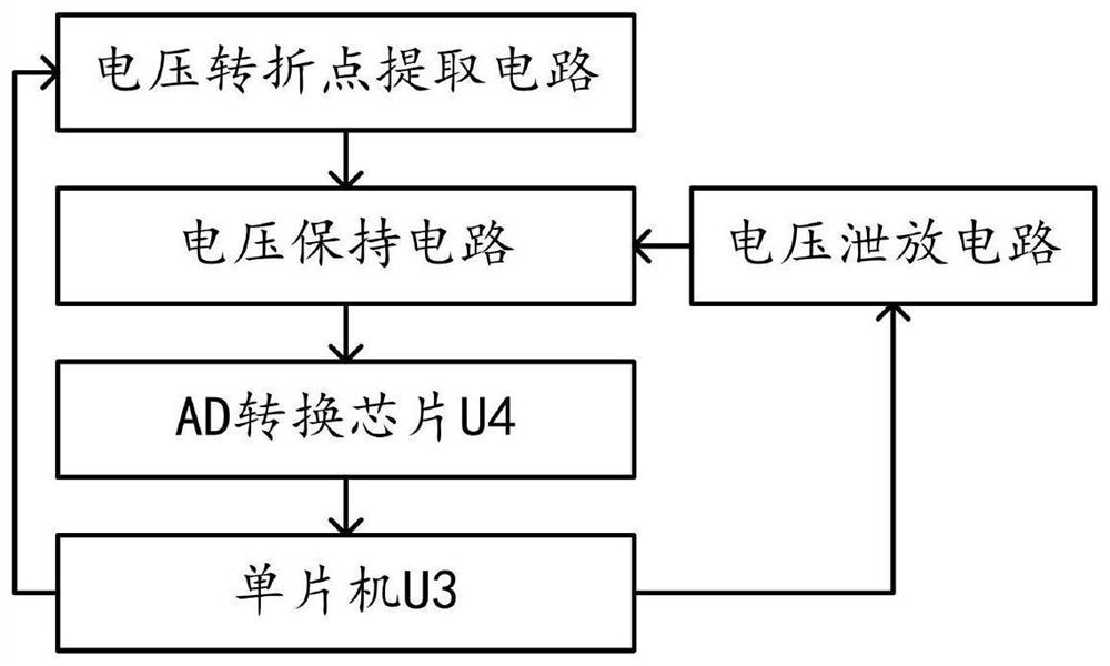
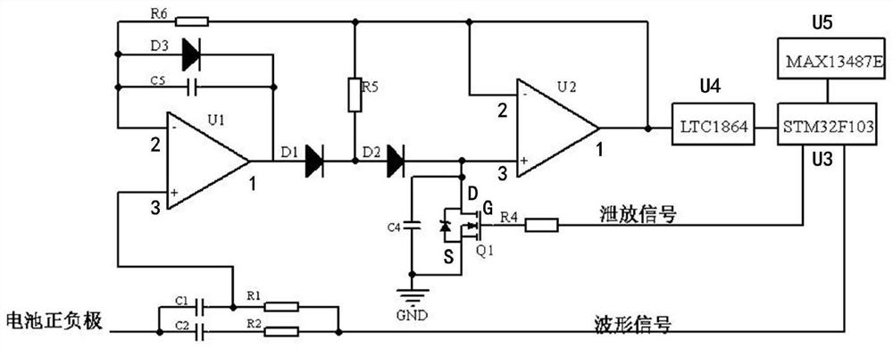
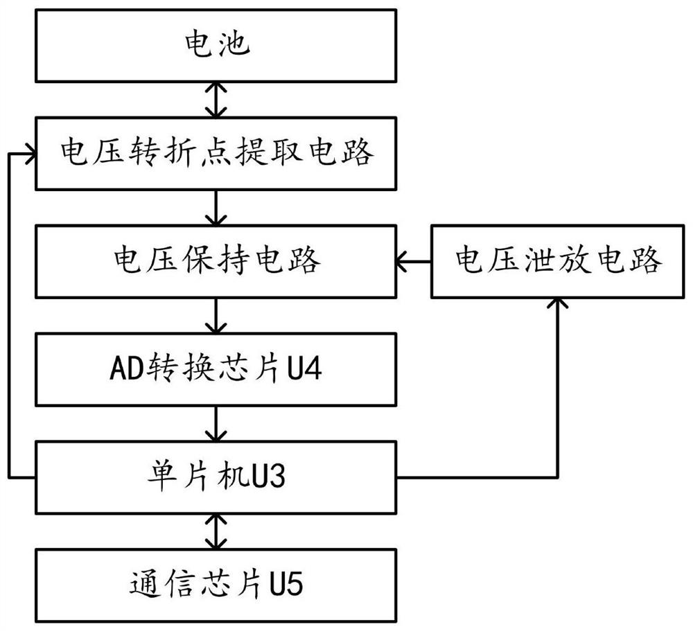
[0056] The general idea of ​​the technical solution in the embodiment of the present application is as follows: by setting the voltage turning point extraction circuit, the curve fitting evaluation is changed into a sampling scheme of taking the maximum value in the interval, reducing the difficulty of sampling the turning voltage of the voltage turning point, and improving the sampling efficiency. Accuracy; by setting the voltage holding circuit to perform voltage holding operation on the turning voltage (peak voltage) generated by the voltage turning point extraction circuit, the voltage sampling accuracy of the AD conversion chip U4 is guaranteed, and the requirement for AD sampling speed is reduced; by setting the voltage discharge circuit The voltage of the capacitor C4 in the voltage holding circuit is discharged to speed up the discharge speed, so as to improve the accuracy and speed of the insulation resistance detection.

[0057] Please refer to Figure 1 to Figure 11...


PUM


Abstract

The invention provides an AC injection insulation resistance detection circuit and method in the technical field of electric vehicles. The detection circuit comprises a single-chip microcomputer U3, an AD conversion chip U4, a voltage holding circuit, a voltage discharge circuit and a voltage turning point extraction circuit. The input end of the voltage holding circuit is connected with the voltage turning point extraction circuit, and the output end of the voltage holding circuit is connected with the AD conversion chip U4; the input end of the single-chip microcomputer U3 is connected with the AD conversion chip U4, and the output end of the single-chip microcomputer U3 is connected with the voltage turning point extraction circuit and the voltage discharge circuit; and the voltage discharge circuit is connected with the voltage holding circuit. The circuit has the advantage that the precision and the speed of insulation resistance detection are greatly improved.

Description

technical field [0001] The invention relates to the technical field of electric vehicles, in particular to an AC injection insulation resistance detection circuit and method. Background technique [0002] With the popularization of electric vehicles, the number of reports on spontaneous combustion incidents of electric vehicles is also increasing, and people begin to pay attention to the safety of electric vehicles, and the insulation of electric vehicle batteries is the most important indicator. For the insulation detection of batteries, there are traditionally two methods: the bridge method and the low-frequency injection method. [0003] Method 1: The test circuit of the bridge method is as follows: Figure 8 As shown, close K1 and K2 respectively to get two sets of equations: [0004] [0005] [0006] By combining the above two sets of equations, the insulation resistance R can be obtained P and insulation resistance R n The resistance value; where U 1 Indicat...

Claims


Application Information

Patent Timeline
Patent Type & Authority Applications(China)
IPC IPC(8): G01R27/02
CPCG01R27/025
Inventor 汤平陈木泉夏章乐章云区
Owner FUJIAN NEBULA ELECTRONICS CO LTD
Why Eureka
Try Eureka