Valve pressing plate wiring device and diesel engine valve control device

A wiring device and valve technology, applied in the direction of engine control, connection, electrical components, etc., can solve the problems of easy tearing of insulating sleeves, easy short circuit, easy rotation of wiring studs, etc., so as to achieve not easy to tear, avoid short circuit, reduce The effect of the short-circuit fault on the probability of occurrence

Pending Publication Date: 2021-06-25
XCMG CONSTR MACHINERY
View PDF3 Cites 0 Cited by
  • Summary
  • Abstract
  • Description
  • Claims
  • Application Information

AI Technical Summary

Problems solved by technology

[0004] The purpose of the present invention is to overcome the deficiencies in the prior art, and provide a valve pressure plate wiring device and a diesel engine valve control device to solve the technical problems in the prior art that the insulating sleeve is easy to tear, and the wiring studs are easy to follow and turn, resulting in easy short circuit.

Method used


Image

  • Valve pressing plate wiring device and diesel engine valve control device
  • Valve pressing plate wiring device and diesel engine valve control device

Examples


Embodiment 1

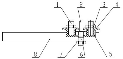
[0024] The embodiment of the present invention provides a valve pressure plate wiring device, such as figure 1 As shown, it includes a wiring assembly and an insulator 5, and the insulator 5 is fixedly connected to the valve pressure plate 8. The wiring assembly includes: a terminal stud 1 and a compression nut 3; one end of the terminal stud 1 is pre-embedded in the insulator 5, so that the terminal stud 1 is fixed in the insulator 5; the other end of the terminal stud 1 is provided with a wire clamp Ring 4, the compression nut 3 is threadedly connected with the terminal stud 1, and is used to compress the wire pressure ring 4, the body of the wire pressure ring 4 is connected with a wire, and the other end of the wire is connected to the positive and negative poles of the two-way electromagnet, thereby Realize leading out the positive and negative wires of the two-way electromagnet in the valve automatic control device.

[0025] One end of the terminal stud 1 provided by th...

Embodiment 2

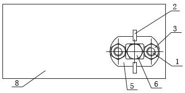
[0030] The embodiment of the present invention also provides a valve control device for a diesel engine, including a valve pressure plate 8 and a valve pressure plate wiring device, specifically:

[0031] Such as figure 1 As shown, it includes a wiring assembly and an insulator 5, and the insulator 5 is fixedly connected to the valve pressure plate 8. The wiring assembly includes: a terminal stud 1 and a compression nut 3; one end of the terminal stud 1 is pre-embedded in the insulator 5, so that the terminal stud 1 is fixed in the insulator 5; the other end of the terminal stud 1 is provided with a wire clamp Ring 4, the compression nut 3 is threadedly connected with the terminal stud 1, and is used to compress the wire pressure ring 4, the body of the wire pressure ring 4 is connected with a wire, and the other end of the wire is connected to the positive and negative poles of the two-way electromagnet, thereby Realize leading out the positive and negative wires of the two-...


PUM


Abstract

The invention discloses a valve pressing plate wiring device and a diesel engine valve control device, belonging to the technical field of electrical equipment. The valve pressing plate wiring device comprises wiring assemblies and an insulator, wherein the insulator is fixedly connected with a valve pressing plate. Each wiring assembly comprises a wiring stud and a compression nut, wherein one end of the wiring stud is pre-buried in the insulator, and the other end of the wiring stud is in threaded connection with the compression nut and is used for compressing a wire compression ring. The number of the wiring assemblies is multiple, an insulating baffle is arranged between every two adjacent wiring assemblies, and the insulating baffles are fixedly connected with the insulator. According to the invention, the wiring device is installed in a molded embedded manner, and the insulator is fixedly connected with the valve pressing plate, so the problem of rotation of the wiring studs is solved; and the insulating baffles are arranged between two adjacent groups of wiring studs, so left and right wire pressing rings can be effectively separated, and short circuit caused by contact of the two wire pressing rings is avoided.

Description

technical field [0001] The invention relates to a valve pressing plate wiring device and a diesel engine valve control device, belonging to the technical field of electrical equipment. Background technique [0002] At present, some decompression starting diesel engines are equipped with automatic valve control devices. The two-way electromagnet in the device needs to lead out the positive and negative wires. Usually, technicians use two sets of wiring studs to lead out the positive and negative wires. A through hole, a tubular insulator is nested in the through hole; the terminal stud penetrates through the insulator, and the two ends are locked and fixed by the compression nut and the valve pressure plate. [0003] However, there are defects in this wiring method. If the tightening torque of the compression nut is too large, it will easily cause the insulation sleeve to tear; In addition, no matter whether the insulating sleeve is torn or the terminal studs are rotated, it...

Claims


Application Information

Patent Timeline
IPC IPC(8): H01R9/22H01R4/30F02D13/02
CPCH01R9/22H01R4/30F02D2013/0292
Inventor 史正文牛刚学井然崔玉艳于洋李想
Owner XCMG CONSTR MACHINERY
Why Eureka
Try Eureka