Rotor, motor, water pump and vehicle
A rotor and rotor core technology, applied in the field of vehicles, can solve the problems of polluting the conveying liquid, corroding the rotor core, etc.
- Summary
- Abstract
- Description
- Claims
- Application Information
AI Technical Summary
Problems solved by technology
Method used
Image
Examples
Embodiment 1
[0098] A rotor 100 (such as Figure 4 shown), including: a rotating shaft 1, a rotor core 2, and a plastic-coated body 46.
[0099] Specifically, the rotor core 2 is provided with a shaft hole 24 and a mounting slot 25 . The permanent magnet 5 is installed in the installation groove 25 . The overmolding body 46 is connected to the rotor core 2 and at least covers the opening end of the mounting slot 25 to encapsulate the permanent magnet 5 in the rotor core 2 .
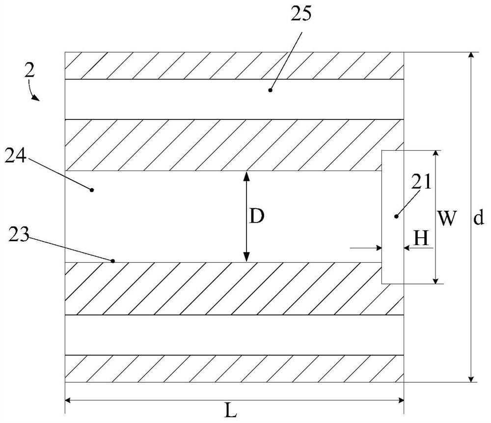
[0100] Wherein, at least one end of the overmolding body 46 is provided with an axial extension, and the radially inner end of the axial extension is flush with the inner surface 23 of the rotor core 2 . The axial extension part can be the filling part 41 , the extension part 45 , or a combination of the filling part 41 and the extension part 45 or other ways.
[0101] By providing an axial extension 45 on at least one end of the overmolding body 46, and the radially inner end of the axial extension is flush with t...
Embodiment 2
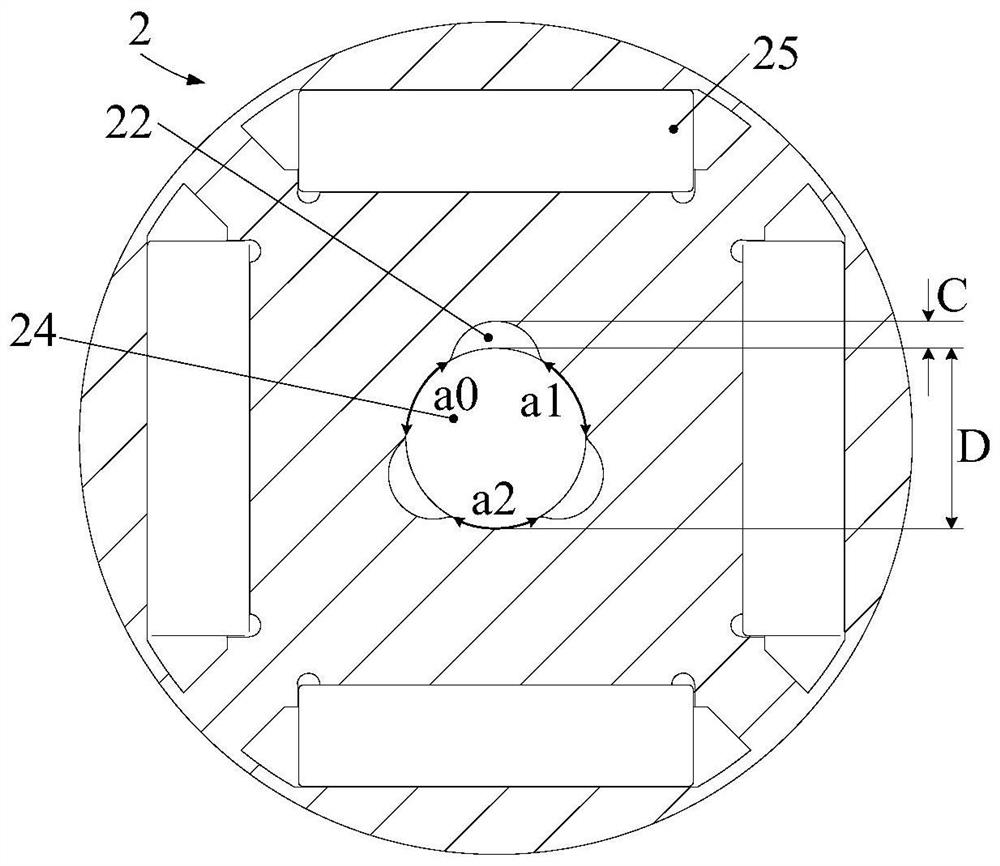
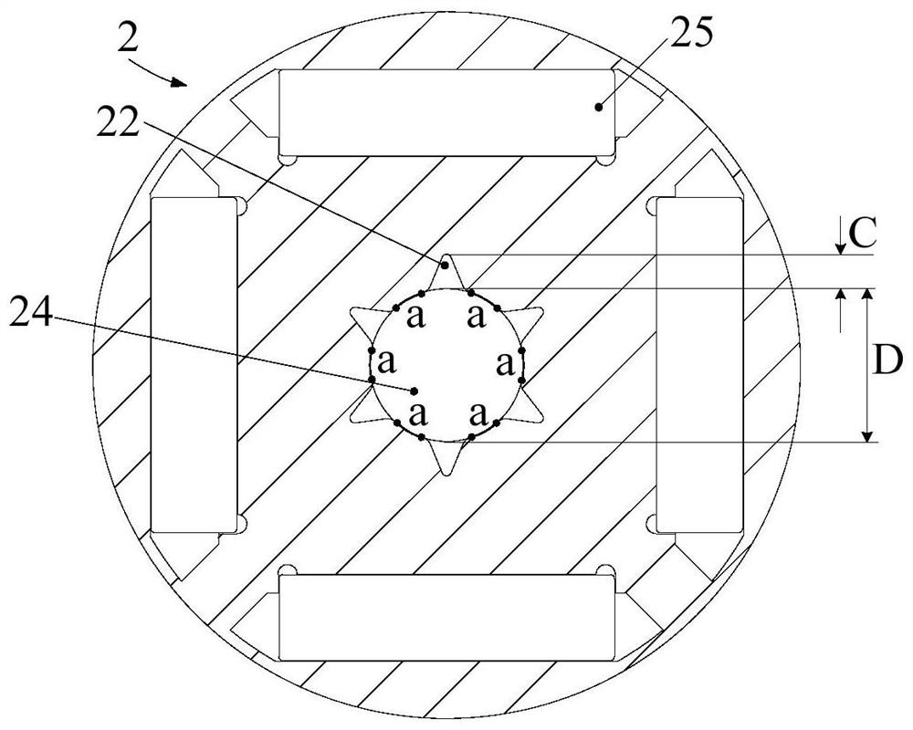
[0121] On the basis of Embodiment 1, further, the inner surface 23 of the rotor core 2 is provided with at least one avoidance slot 22, such as figure 2 and image 3 shown. The escape slot 22 runs through at least one end surface of the rotor core 2 along the rotor axial direction.
[0122] In the prior art, when the rotating shaft 1 is interference-fitted with the shaft hole 24 , there is a problem that the rotating shaft 1 is easily bent when the rotating shaft 1 is installed into the rotor core 2 due to excessive pressing force. However, in the present application, an avoidance groove 22 is provided on the inner surface 23 of the rotor core 2, which can reduce the contact area between the rotor core 2 and the rotating shaft 1, thereby reducing the friction between the rotating shaft 1 and the rotor core 2 during assembly, that is, reducing the pressure. The frictional force received when the rotating shaft 1 is inserted is beneficial to assembly, thereby preventing the r...
Embodiment 3
[0144] The difference from Embodiment 1 or Embodiment 2 is that: the axial extension part includes an extension part 45, such as Figure 10 shown. The extension part 45 is provided on the end surface of the overmolding body 46 and extends in a direction away from the rotor core 2 along the axial direction of the rotor.
PUM
| Property | Measurement | Unit |
|---|---|---|
| Axial depth | aaaaa | aaaaa |
Abstract
Description
Claims
Application Information
 - R&D
- Intellectual Property
- Life Sciences
- Materials
- Tech Scout
- Unparalleled Data Quality
- Higher Quality Content
- 60% Fewer Hallucinations
Browse by: Latest US Patents, China's latest patents, Technical Efficacy Thesaurus, Application Domain, Technology Topic, Popular Technical Reports.
© 2025 PatSnap. All rights reserved.Legal|Privacy policy|Modern Slavery Act Transparency Statement|Sitemap|About US| Contact US: help@patsnap.com


