Fault positioning system and method based on video image diagnosis data

A fault location, video image technology, applied in the direction of image communication, television, electrical components, etc., can solve the problems of inability to locate, alarm data faults cannot be located, etc., and achieve the effect of improving efficiency

Active Publication Date: 2021-06-25
CRSC COMM & INFORMATION GRP CO LTD
View PDF8 Cites 4 Cited by
  • Summary
  • Abstract
  • Description
  • Claims
  • Application Information

AI Technical Summary

Problems solved by technology

However, there are still the following problems in the process of on-site operation and maintenance: the video image quality system diagnoses the video image, but cannot determine the cause of the image problem and cannot locate the cause of the fault; the video network management system collects rich video surveillance system software and hardware through multiple channels Equipment data, and realize the visual monitoring data display, but there are problems that the alarm data is simply stacked and presented, and the fault cannot be located

Method used


Image

  • Fault positioning system and method based on video image diagnosis data
  • Fault positioning system and method based on video image diagnosis data
  • Fault positioning system and method based on video image diagnosis data

Examples


Embodiment 1

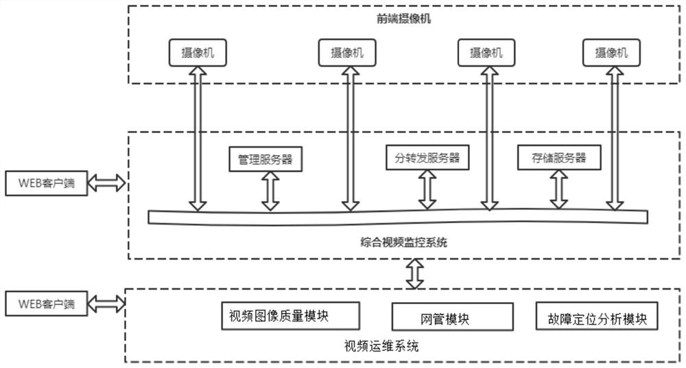
[0046] like figure 1 As shown, the fault location system based on video image diagnosis data provided by the embodiment of the present invention includes a front-end equipment camera system, an integrated video monitoring system, and a video operation and maintenance system.

[0047] The front-end equipment camera system includes all-channel cameras for capturing video image information;

[0048] The integrated video monitoring system is connected to the front-end equipment camera system for viewing real-time video and recorded video;

[0049]The video operation and maintenance system is connected to the comprehensive video surveillance system, which is used to diagnose the quality of the acquired video images, determine the type of video surveillance fault, and locate the cause of the fault. Among them, both the integrated video monitoring system and the video operation and maintenance system can exchange information with the WEB client.

[0050] Specifically, the video ope...

Embodiment 2

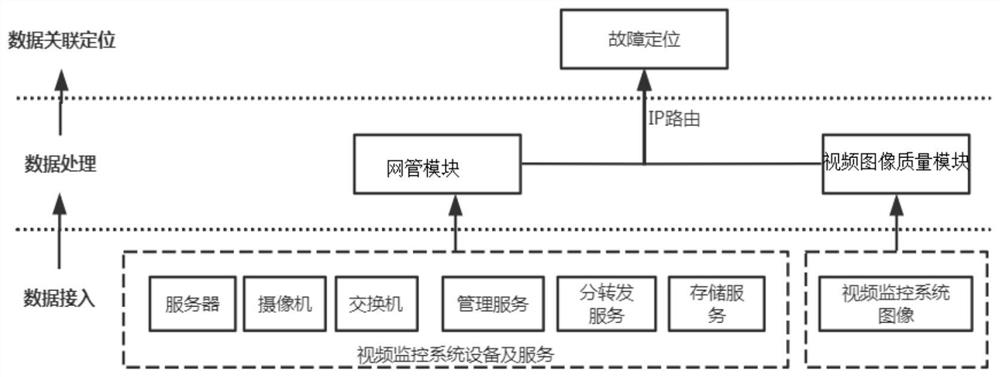
[0060] like figure 2 As shown, the fault location method based on video image diagnosis data provided in this embodiment includes data collection, data processing, data quality diagnosis and data association location, the specific content is:

[0061] S1. Data collection

[0062] Specifically, the data collection includes two types, hardware device and software system data.

[0063] Hardware devices connect all cameras, switches, servers and other hardware devices to the network management server for processing through multi-protocol IPMI\SNMP\Zabbix Agent\Restful\TCP\PING\Iron standard video data interface and other customizable interfaces.

[0064] The data of the software system connects the data of the integrated video monitoring system to the image diagnosis server through the iron standard A interface for processing.

[0065] S2, data processing

[0066] Specifically, data convergence is performed on the collected data first, and the same or similar data in continuou...


PUM


Abstract

The invention relates to a fault positioning system and method based on video image diagnosis data, and the system comprises a front-end equipment camera system which comprises a full-path camera and is configured to shoot video image information; a comprehensive video monitoring system which is configured to check the real-time video and the recorded video shot by the front-end equipment camera system; and a video operation and maintenance system which is configured to perform quality diagnosis on the video images acquired by the comprehensive video monitoring system to determine video monitoring fault types and position fault causes. The method can be used for centralized management and operation and maintenance of video service related equipment and systems, provides intelligent service of fault positioning analysis for users, assists operation and maintenance management personnel in judging the safety and stability of video operation, and provides powerful support for production operation and maintenance decision making.

Description

technical field [0001] The invention relates to a fault location system and method based on video image diagnosis data, and relates to the technical fields of network communication and video monitoring and monitoring. Background technique [0002] The video operation and maintenance management system applies Internet, big data and other technologies to realize intelligent operation and maintenance of railway video surveillance, which is a response to the transformation and upgrading of railway video from traditional infrastructure to intelligent transportation infrastructure. The railway integrated video surveillance system monitors a wide range, and the access capacity of cameras on the whole road has reached a scale of more than 100,000 roads. Users need to monitor around the clock, so the demand for operation and maintenance monitoring is becoming stronger. [0003] The existing operation and maintenance platform includes a video image quality diagnosis system and a video...

Claims


Application Information

Patent Timeline
Patent Type & Authority Applications(China)
IPC IPC(8): H04N17/00
CPCH04N17/002
Inventor 徐亚萍杨天骄张景峰关祚
Owner CRSC COMM & INFORMATION GRP CO LTD
Why Eureka
Try Eureka