Emulsifying and dispersing machine

An emulsifying and dispersing, dispersing machine technology, applied in mixers, chemical instruments and methods, chemical/physical processes, etc., can solve the problems that the upper raw materials cannot be sheared and emulsified, the effect of emulsification and dispersion is affected, and the material flow and mixing is slow. Achieve the effect of improving emulsification and dispersion efficiency, improving emulsification efficiency and production efficiency, and prolonging service life

Pending Publication Date: 2021-06-29
上海睿迈机械科技有限公司
View PDF0 Cites 1 Cited by
  • Summary
  • Abstract
  • Description
  • Claims
  • Application Information

AI Technical Summary

Problems solved by technology

The emulsifying dispersing machine in the prior art mainly has the following problems: 1. When the existing emulsifying dispersing machine is used, it is easy to make particles and cohesive blocks in the mixture difficult to be dispersed, thereby affecting the emulsifying and dispersing effect; 2. Stator and rotor During the operation of the component structure, the raw materials rotate with the rotation of the rotor, causing the raw materials to vortex, and the upper layer of materials cannot flow downward, resulting in the upper layer of raw materials not being sheared and emulsified, thus affecting the emulsification effect; 3. The viscosity is relatively high When the large material is emulsified and dispersed in the emulsification disperser, the flow and mixing of the material is relatively slow, which cannot ensure sufficient dispersion and emulsification

Method used


Image

  • Emulsifying and dispersing machine
  • Emulsifying and dispersing machine
  • Emulsifying and dispersing machine

Examples


Embodiment 1

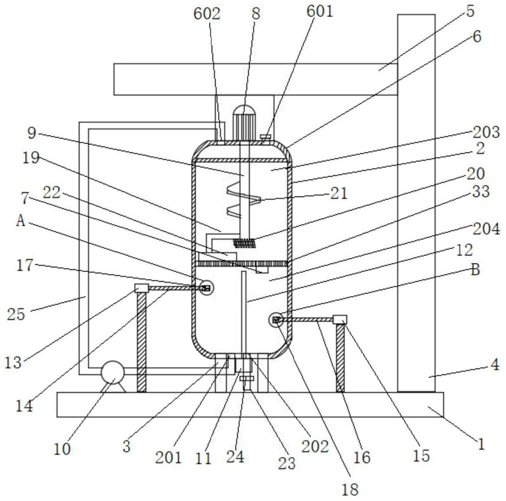
[0044] Such as figure 1 As shown, an emulsifying dispersing machine includes a fixed base 1, a kettle body 2 and an emulsifying and dispersing mechanism; the kettle body 2 is fixed on the upper end surface of the fixed base 1 through a shock absorbing support 3, and an electric telescopic column is also installed on the upper end surface of the fixed base 1 4. A support arm 5 is installed on the top of the electric telescopic column 4, and a kettle cover 6 for covering the kettle body 2 is installed on the lower end surface of the support arm 5; Dispersion zone 203, second emulsification dispersion zone 204.

[0045] In this embodiment, the bottom of the filter plate 33 is fixed with a vibrator 7 , through which the materials on the filter plate 33 are more conducive to entering the second emulsification and dispersion area 204 .

[0046] Such as Figure 4 As shown, the shock absorbing support 3 includes a fixed sleeve 3001, a bearing column 3002, a spring 3003 and a leg 300...

Embodiment 2

[0063] Such as Figure 5 and Figure 6 As shown, the structural difference between the emulsifying dispersing machine in this embodiment and Embodiment 1 is: in this embodiment, the first rotating shaft 9 is positioned at the bottom of the first emulsifying and dispersing area 203, and a U-shaped stirring blade 26 is provided, and the U-shaped stirring blade 26 is provided with an arc-shaped diversion notch 27 on the side facing the inner wall of the kettle body 2, and an arc-shaped diversion protrusion 28 distributed along the radial direction is provided on the inner wall of the kettle body 2, and the arc-shaped diversion protrusion The central axis of 28 is parallel to the central axis of the arc-shaped guide notch 27 and located on the same horizontal plane.

[0064] When the emulsification disperser in this embodiment is in use, the arc-shaped flow guide gap 27 on the U-shaped stirring blade 26 cooperates with the arc-shaped flow guide protrusion 28 on the inner wall of ...

Embodiment 3

[0066] Such as Figure 7 As shown, the structural difference between the emulsifying and dispersing machine in this embodiment and Embodiment 1 is that: in this embodiment, an insulating layer 29 is provided on the outer wall of the kettle body 2, and an electrical insulation layer 29 is arranged between the insulating layer 29 and the outer wall of the kettle body 2. The heating wire 30 and the temperature sensor 31 are installed on the inner wall of the second emulsification dispersion area 204 , and the fixed base 1 is also provided with a controller 32 , and the controller 32 is connected to the electric heating wire 30 and the temperature sensor 31 respectively.

[0067] Wherein, the controller 32 in this embodiment is a REX-C100 electronic temperature controller.

[0068] When the emulsifying disperser in this embodiment is in use, the temperature inside the kettle body 2 is controlled through the joint action of the electric heating wire 30, the temperature sensor 31 an...


PUM


Abstract

The invention discloses an emulsifying and dispersing machine. The machine comprises a fixed base, a kettle body and an emulsifying and dispersing mechanism; the kettle body is fixed to the upper end face of the fixed base through a damping support, an electric telescopic column is further installed on the upper end face of the fixed base, a supporting arm is installed at the top of the electric telescopic column, and a kettle cover for covering the kettle body is installed on the lower end face of the supporting arm; and the kettle cover is provided with a first feed port and a second feed port, the bottom of the kettle body is provided with a first discharge port and a second discharge port, the first discharge port is connected with a first discharge pipe, the first discharge pipe is provided with a discharge valve, the second discharge port is communicated with the second feed port through a second discharge pipe, and the second discharge pipe is provided with an emulsification pump. The material emulsification and dispersion efficiency is high, the emulsification quality is high, and the material in the kettle body can be further crushed so as to form the internal circulation, such that the emulsification dispersion uniformity is improved, and the emulsification dispersion efficiency and the emulsification quality are further improved.

Description

technical field [0001] The invention relates to the technical field of emulsification dispersers, in particular to an emulsification disperser. Background technique [0002] The emulsifying dispersing machine is a high-speed dispersing and grinding dual-purpose machine, which is suitable for stirring, dissolving and dispersing various liquids. Through the powerful high-speed shearing function, the product can meet the requirements of emulsifying and dispersing in a short time. The emulsifying dispersing machine in the prior art mainly has the following problems: 1. When the existing emulsifying dispersing machine is used, it is easy to make particles and cohesive blocks in the mixture difficult to be dispersed, thereby affecting the emulsifying and dispersing effect; 2. Stator and rotor During the operation of the component structure, the raw materials rotate with the rotation of the rotor, causing the raw materials to vortex, and the upper layer of materials cannot flow dow...

Claims


Application Information

Patent Timeline
IPC IPC(8): B01F13/10B01F7/18B01F11/02B01F3/08
CPCB01F23/41B01F27/90B01F31/80B01F33/8305
Inventor 卞红胜
Owner 上海睿迈机械科技有限公司
Why Eureka
Try Eureka