Positioning tool for milling side wall of U-shaped workpiece

A technology for positioning tooling and workpieces, which is applied in the field of positioning tooling for side wall milling. It can solve the problems of no comparison files, large elastic deformation, and difficult locking and positioning, so as to improve processing efficiency and processing accuracy, and facilitate positioning and disassembly. Avoid the effect of inward bending deformation

Inactive Publication Date: 2021-06-29
天津市臣涛精密机械设备有限公司
View PDF0 Cites 0 Cited by
  • Summary
  • Abstract
  • Description
  • Claims
  • Application Information

AI Technical Summary

Problems solved by technology

[0002] In the field of workpiece machining, workpiece side wall cleaning is one of the more common machining processes, but in the prior art, the clamping tooling for workpiece side wall cleaning cannot complete U-shaped workpiece side wall milling with reserved holes Due to the large elastic deformation caused by the structural characteristics of the U-shaped workpiece, it is extremely difficult to ensure the locking and positioning of the two straight side walls of the U-shaped workpiece during the groove milling process. If the side wall clamping is used blindly If the method is used, the two straight sides of the U-shaped workpiece will be bent inwardly. If the internal support method is used, the problem of the torsional swing of the U-shaped workpiece cannot be solved. Therefore, a side wall milling machine that can quickly clamp the U-shaped workpiece is urgently needed. Face tooling
[0003] Through the search of public patents, no relevant comparative documents were found

Method used


Image

  • Positioning tool for milling side wall of U-shaped workpiece
  • Positioning tool for milling side wall of U-shaped workpiece
  • Positioning tool for milling side wall of U-shaped workpiece

Examples


Embodiment Construction

[0015] In order to further understand the content, characteristics and effects of the present invention, the following examples are given, and detailed descriptions are given below with reference to the accompanying drawings. It should be noted that this embodiment is descriptive, not restrictive, and cannot thereby limit the protection scope of the present invention.

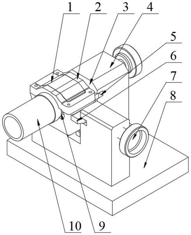
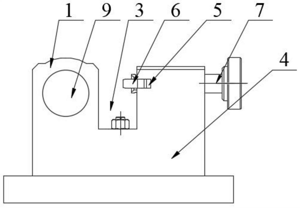
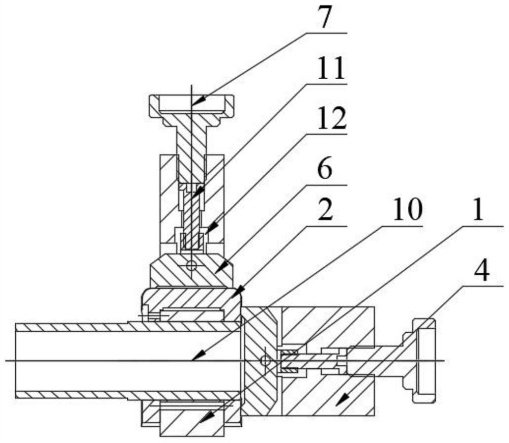
[0016] A positioning tool for side wall milling of a U-shaped workpiece. Coaxial reserved holes are formed on the two straight side walls of the U-shaped workpiece 2. The positioning tool includes a bottom plate 8 fixed on the top surface of the bottom plate. There is a right-angle bracket 4; the middle corner of the right-angle bracket is integrally made with a workpiece positioning seat 1 for suit positioning U-shaped workpieces, and the middle part of the two right-angle sides on the top surface of the right-angle bracket is provided with a relief groove 3, and the two right-angle brackets A through hole 12 ...


PUM


Abstract

The invention discloses a positioning tool for milling the side wall of a U-shaped workpiece. The tool comprises a bottom plate, and a right-angle support is fixedly installed on the top surface of the bottom plate. A workpiece positioning seat is integrally made at the corner of the middle of the right-angle support, receding grooves are formed in the middles of the two right-angle edges of the top surface of the right-angle support, and through holes are formed in the two right-angle edges of the right-angle support. An ejecting unit is connected into a through hole in an adjusting manner, and the output end of the ejecting unit axially penetrates through the through hole and extends into the receding grooves. A pin hole penetrating in the horizontal direction is formed in the workpiece positioning seat, and a positioning pipe pin is movably inserted into the pin hole. The two ends of the positioning pipe pin penetrate through preformed holes in the side walls of the two straight edges of the U-shaped workpiece respectively. According to the positioning tool, an inner support can be formed in the U-shaped workpiece, meanwhile, the preformed holes of the U-shaped workpiece can be positioned and locked, and the U-shaped workpiece is firmly pressed on the workpiece positioning seat in an ejecting manner through the ejecting unit in the end; and the positioning tool is simple in structure, convenient to position and suitable for side wall face milling of a large batch of U-shaped workpieces.

Description

technical field [0001] The invention relates to the technical field of mechanical tooling, in particular to a positioning tool for side wall milling of a U-shaped workpiece. Background technique [0002] In the field of workpiece machining, workpiece side wall cleaning is one of the more common machining processes, but in the prior art, the clamping tooling for workpiece side wall cleaning cannot complete U-shaped workpiece side wall milling with reserved holes Due to the large elastic deformation caused by the structural characteristics of the U-shaped workpiece, it is extremely difficult to ensure the locking and positioning of the two straight side walls of the U-shaped workpiece during the groove milling process. If the side wall clamping is used blindly If the method is used, the two straight sides of the U-shaped workpiece will be bent inwardly. If the internal support method is used, the problem of the torsional swing of the U-shaped workpiece cannot be solved. Theref...

Claims


Application Information

Patent Timeline
Patent Type & Authority Applications(China)
IPC IPC(8): B23Q3/06
CPCB23Q3/062
Inventor 崔超崔越崔文来崔建涛崔雅臣李绍功张涛李绍德
Owner 天津市臣涛精密机械设备有限公司
Why Eureka
Try Eureka