Tool placing frame for machining lathe and using method of tool placing frame

A technology for machining and placing racks, which is applied in the direction of manufacturing tools, metal processing equipment, metal processing machinery parts, etc., can solve the problems of inconvenient access, troublesome storage, inconvenient access to tools, etc., to achieve convenient tool search and operation. Convenience and the effect of improving the replacement rate

Inactive Publication Date: 2021-06-29
聂旭旗
View PDF0 Cites 0 Cited by
  • Summary
  • Abstract
  • Description
  • Claims
  • Application Information

AI Technical Summary

Problems solved by technology

[0003] And the existing machining lathe is inconvenient to rotate with the cutting tool rack, when the personnel is changing the cutting tool of the lathe, because the knives in different positions of the rack are different, it is inconvenient for the staff to take and use, and the rack is not easy to rotate, causing the staff to be in the When changing the tool, it is troublesome to take and store it from the shelf, which is not conducive to the use of personnel, and the existing tool shelf for machining lathes is not convenient for personnel to access the tool. It is relatively inconvenient, and at the same time, the existing tool holders for machining lathes do not have the marking function. When personnel change the tools on the lathe, because the models and sizes of the tools are often different, they do not have the marking function. Searching for a long time will affect the efficiency of personnel replacement

Method used


Image

  • Tool placing frame for machining lathe and using method of tool placing frame
  • Tool placing frame for machining lathe and using method of tool placing frame
  • Tool placing frame for machining lathe and using method of tool placing frame

Examples


Embodiment Construction

[0024] The following will clearly and completely describe the technical solutions in the embodiments of the present invention with reference to the accompanying drawings in the embodiments of the present invention. Obviously, the described embodiments are only some, not all, embodiments of the present invention. Based on the embodiments of the present invention, all other embodiments obtained by persons of ordinary skill in the art without making creative efforts belong to the protection scope of the present invention.

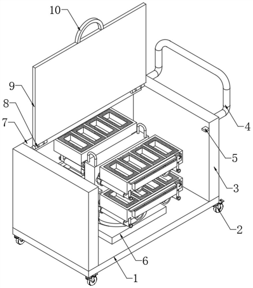
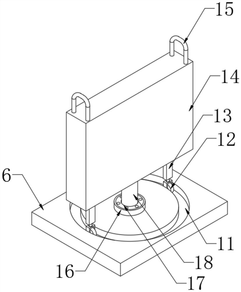
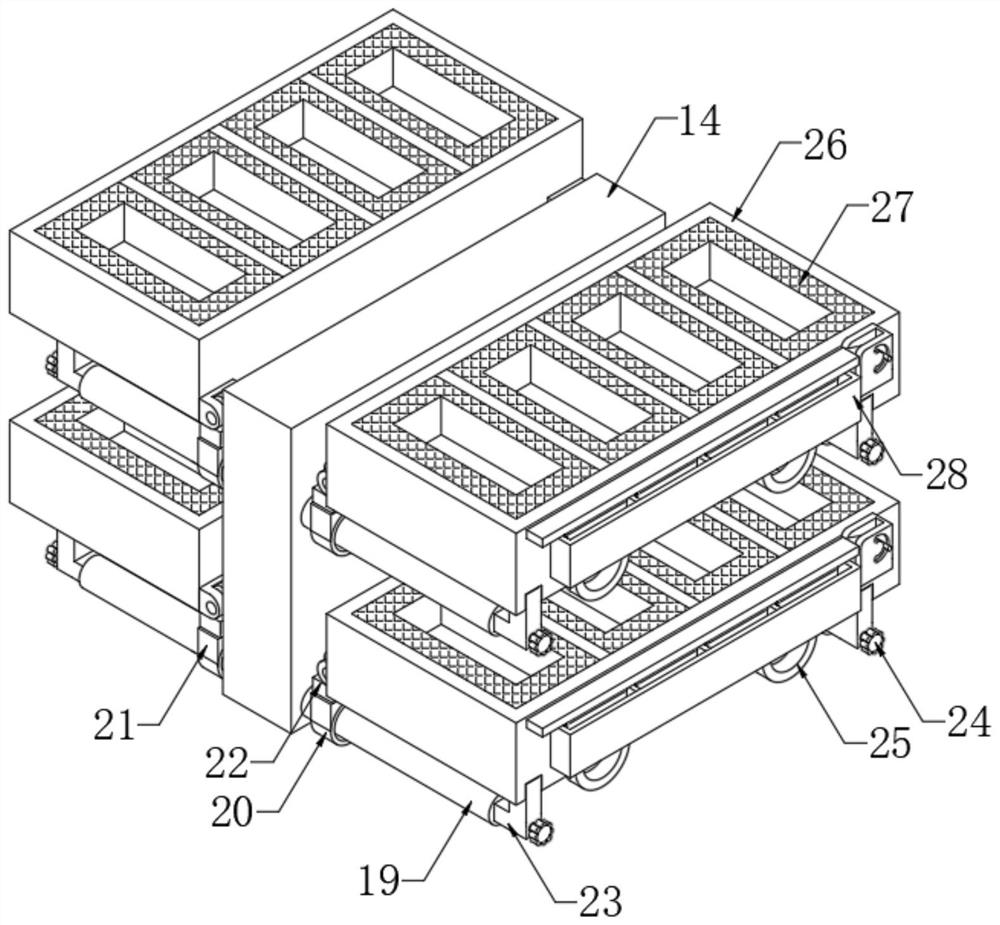
[0025] The present invention provides such Figure 1-6 The shown tool placement frame for machining lathes and its use method includes a bottom plate 1, movable casters 2 are fixed at the four corners of the bottom end of the bottom plate 1, and side plates are fixed on both sides of the top end of the bottom plate 1 3. The middle part of the top of the bottom plate 1 is fixed with a connecting plate 6, and the middle part of the top of the connecting plate 6 ...


PUM


Abstract

The invention discloses a tool placing frame for a machining lathe and a using method of the tool placing frame. The tool placing frame comprises a bottom plate, wherein movable trundles are fixedly arranged at the four corners of the bottom end of the bottom plate, side plates are fixedly arranged on the two sides of the top end of the bottom plate, a connecting plate is fixedly arranged in the middle of the top end of the bottom plate, and a bearing seat is fixedly arranged in the middle of the top end of the connecting plate; and a rotating bearing is fixedly mounted on the inner wall of the bearing seat, the inner wall of the rotating bearing is rotationally connected with the bottom of the outer wall of a rotating shaft, the top end of the rotating shaft is fixedly connected with the middle of the bottom end of a supporting plate, and pulling handles are fixedly arranged on the two sides of the top end of the supporting plate correspondingly. The rotating bearing is arranged in the bearing seat connected through the connecting plate, the rotating bearing is rotationally connected with the rotating shaft connected with the supporting plate, a supporting rod connected with the supporting plate is connected with a limiting universal wheel, and the limiting universal wheel is connected with a limiting circular groove formed in a connecting plate in a penetrating and inserting mode, so that the placing frame can be rotated more conveniently, personnel can rotate the placing frame by rotating the supporting plate, and the personnel is guaranteed to take and use cutters on the two sides of the placing frame.

Description

technical field [0001] The invention relates to the technical field of mechanical processing, in particular to a tool placement frame for a mechanical processing lathe and a use method thereof. Background technique [0002] Processing lathes are machines that use cutting tools to turn rotating processing parts. With the continuous development of numerical control technology, processing lathes play an increasingly important role in the development of some livelihood industries. When using a processing lathe, it is necessary to use a tool rack to store the lathe tools. [0003] And the existing machining lathe is inconvenient to rotate with the cutting tool rack, when the personnel is changing the cutting tool of the lathe, because the knives in different positions of the rack are different, it is inconvenient for the staff to take and use, and the rack is not easy to rotate, causing the staff to be in the When changing the tool, it is troublesome to take and store it from th...

Claims


Application Information

Patent Timeline
Patent Type & Authority Applications(China)
IPC IPC(8): B23Q13/00
CPCB23Q13/00
Inventor 聂旭旗
Owner 聂旭旗
Why Eureka
Try Eureka