Intelligent cable processing equipment for electrical engineering
A technology of intelligent processing and electrical engineering, applied in the field of cable processing, can solve the problems that the cable end is not easy to be fixed and clamped, and the wire reel cannot be quickly switched, so as to achieve continuous coiling without stopping, rapid switching, and simple structure Effect
- Summary
- Abstract
- Description
- Claims
- Application Information
AI Technical Summary
Problems solved by technology
Method used
Image
Examples
Embodiment 1
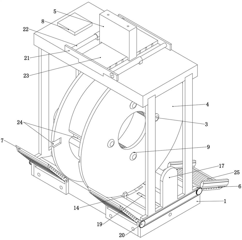
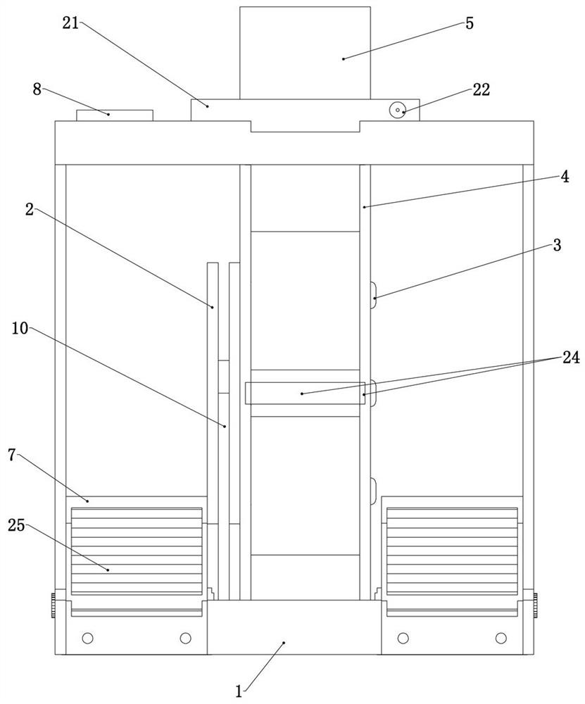
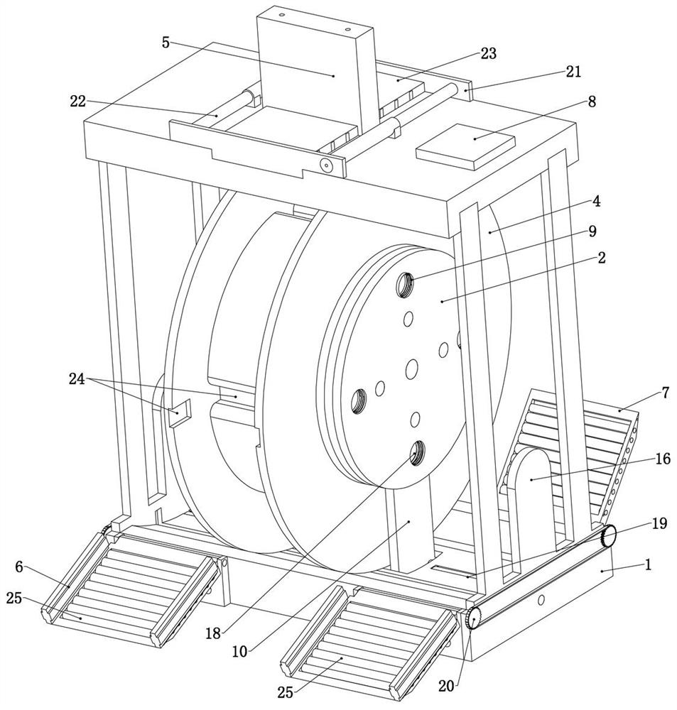
[0050] Embodiment 1, the present invention is an intelligent cable processing equipment for electrical engineering, which is characterized in that it includes a base 1, a drive plate 2 slidably connected to the base 1, and a drive plate slidably connected to the drive plate 2. Shaft 3, wire reel 4 detachably placed on the driving disk 2, snap cylinder 5 arranged above the driving disk 2, front slant plate 6 rotating on one side of the base 1 respectively, respectively arranged on the opposite side of the front hypotenuse The rotation is connected to the back ramp 7 and the control module 8 on the base 1, wherein:
[0051] Base 1: The base 1 is used to provide a fixed foundation for the subsequent structure. The base 1 is fixed to the ground by anchor bolts. The upper end surface of the base 1 is an arc-shaped surface whose center is above the base 1. The arc-shaped surface The diameter of the arc is the same as the diameter of the wire reel 4, the wire reel 4 can slide in the ...
Embodiment 2
[0067] Embodiment two, on the basis of embodiment one, refer to Image 6 , the base 1 is slidably connected with a drive base 10, the drive plate 2 is rotatably connected to the drive base 10, the drive base 10 slides left and right to drive the drive plate 2 to slide left and right on the base 1, here The left and right sliding direction is to move along the axis direction of the arc surface, and the drive side is a hollow disc shape. The drive disc 2 is connected with a central gear 11 for rotation, and the central gear 11 is coaxial with the drive disc 2. The central gear 11 is meshed with a relay gear 12 that is rotatably connected to the drive disc 2, and each of the transfer gears 12 is meshed with a drive gear 13 that is rotatably connected to the drive disc 2. The rotation of the central gear 11 can be driven by the transfer gear 12. Drive gear 13 rotates, central gear 11 and central power source, central power source and described control module 8 are electrically con...
Embodiment 3
[0070] Embodiment 3, on the basis of Embodiment 1, both sides of the drive substrate 10 are fixedly connected with grippers 14, refer to Image 6 , Figure 7 , both sides of the driving substrate 10 are fixedly connected with connecting rods, and the other end of the connecting rod is fixedly connected with the jaw 14, the length of the connecting rod is the same as the thickness of the reel 4, the connecting rod is located below the arc surface, and the jaws 14. The upper end is located above the arc surface;
[0071] Both sides of the drive base 10 are provided with drive hydraulic cylinders 15 fixedly connected in the base 1, and one end of the drive hydraulic cylinders 15 on both sides is in contact with the drive base 10, and the drive hydraulic cylinder 15 can be stretched to drive the drive base 10 synchronously. Movement, the driving hydraulic cylinder 15 is located below the arc surface, and the driving hydraulic cylinders 15 on both sides are connected through pipel...
PUM
 Abstract
Description
Claims
Application Information
 - R&D
- Intellectual Property
- Life Sciences
- Materials
- Tech Scout
- Unparalleled Data Quality
- Higher Quality Content
- 60% Fewer Hallucinations
Browse by: Latest US Patents, China's latest patents, Technical Efficacy Thesaurus, Application Domain, Technology Topic, Popular Technical Reports.
© 2025 PatSnap. All rights reserved.Legal|Privacy policy|Modern Slavery Act Transparency Statement|Sitemap|About US| Contact US: help@patsnap.com


