
Overturning plate type bio-membrane reactor

A technology of biofilm reactor and turning plate, which is applied in the field of water treatment, can solve the problems of incomplete backwashing of biofilm reactor carrier filler, complicated reaction condition control activated sludge method, etc. Good effect, cheap effect

Active Publication Date: 2021-06-29
JIANGSU UNIV
View PDF8 Cites 0 Cited by
  • Summary
  • Abstract
  • Description
  • Claims
  • Application Information

AI Technical Summary

Problems solved by technology

However, in the practical application of the biofilm method, there are often problems such as incomplete backwashing of the carrier packing of the biofilm reactor, and the control of reaction conditions in the reactor is more complicated than that of the activated sludge method.

Method used


Image

  • Overturning plate type bio-membrane reactor
  • Overturning plate type bio-membrane reactor
  • Overturning plate type bio-membrane reactor

Examples


Embodiment 1

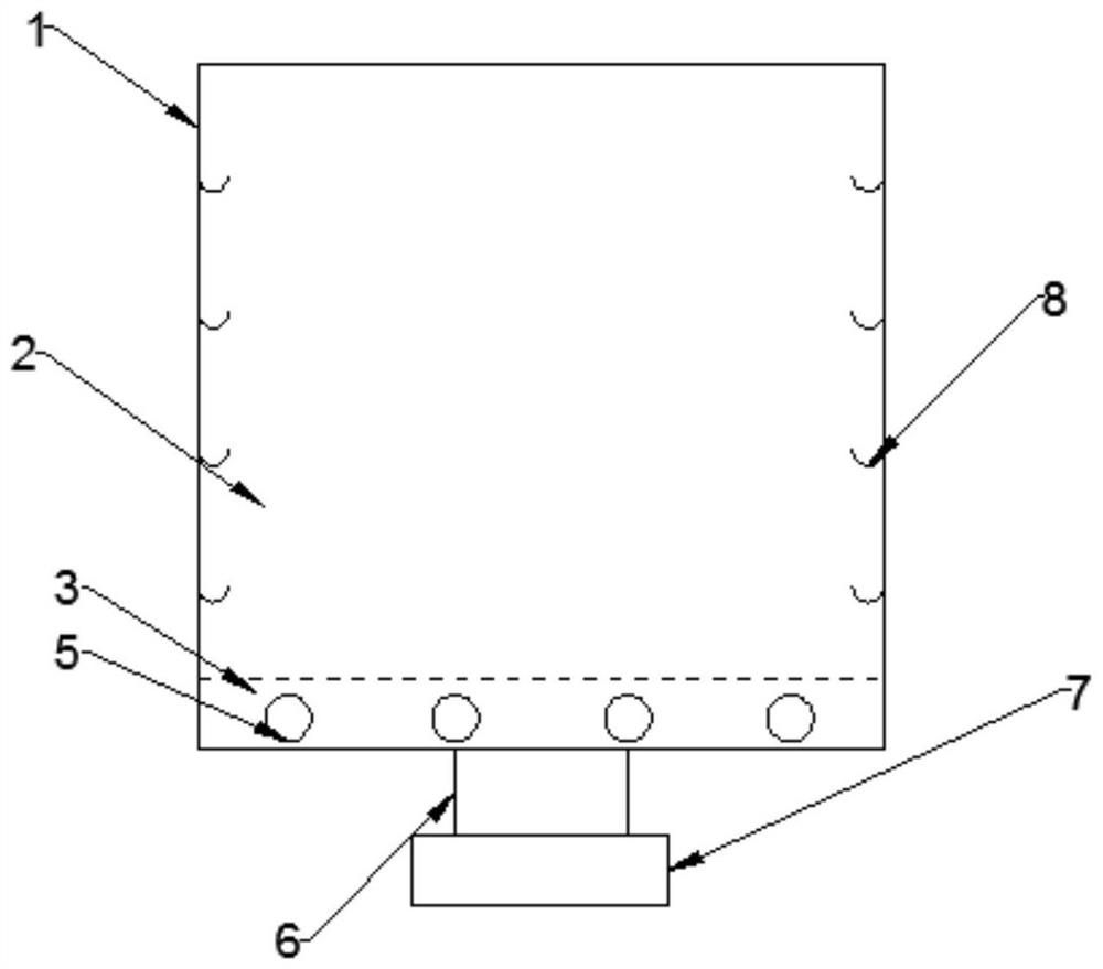
[0028] Such as Figure 1 to Figure 5 As shown, an inverted plate biofilm reactor includes a reactor shell 1, an inverted plate carrier area 2 and an aeration area 3, and the inverted plate carrier area 2 is on the upper part of the aeration area 3. The flip plate carrier area 2 includes multiple sets of flip plate carrier assemblies; the aeration area 3 is provided with microporous aeration heads 5 . A sludge outlet 6 and a valve 7 are provided at the middle of the bottom of the aeration zone 3 to control the discharge of sludge.

[0029] The reactor shell 1 is cylindrical, preferably made of stainless steel; the inner wall of the reactor shell 1 is evenly provided with a plurality of crotches 8 for fixing the flip plate carrier assembly, preferably, the number of the crotch 8 is 2 times the number of board carrier components.

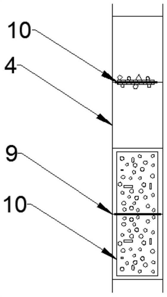
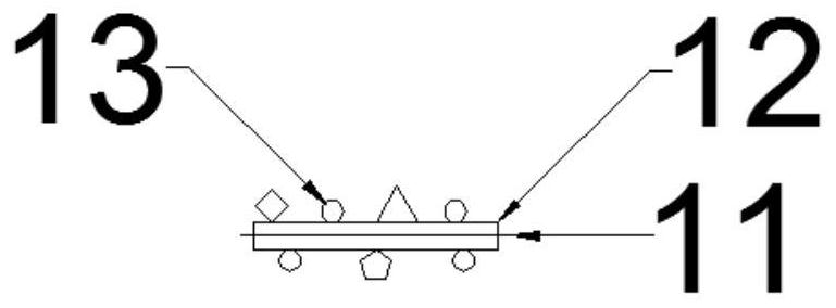
[0030] The flip plate carrier assembly includes a carrier skeleton 4 and a square rotating carrier 10 . Wherein, the carrier frame 4 is formed by a...

Embodiment 2

[0035] An inverted plate biofilm reactor comprises a reactor shell 1, an inverted plate carrier area 2 and an aeration area 3, and the inverted plate carrier area 2 is at the upper part of the aeration area 3. The flip plate carrier area 2 includes multiple sets of flip plate carrier assemblies; the aeration area 3 is provided with microporous aeration heads 5 . A sludge outlet 6 and a valve 7 are provided at the middle of the bottom of the aeration zone 3 to control the discharge of sludge.

[0036] The reactor shell 1 is a cube, preferably, the material is plexiglass; the inner wall of the reactor shell 1 is uniformly provided with a plurality of crotches 8 for fixing the flip plate carrier assembly, preferably, the number of the crotch 8 is 2 4 times the number of board carrier components.

[0037]The flip plate carrier assembly includes a carrier skeleton 4 and a square rotating carrier 10 . Wherein the carrier skeleton 4 is made of a rectangular structure connected by b...


PUM

PropertyMeasurementUnit
Diameteraaaaaaaaaa
Diameteraaaaaaaaaa
Sizeaaaaaaaaaa

Abstract

The invention provides an overturning plate type bio-membrane reactor, which is composed of a reactor shell, an overturning plate carrier area and an aeration area, wherein the overturning plate carrier area is arranged on the upper portion of the aeration area, the overturning plate carrier area consists of a plurality of groups of overturning plate carrier assemblies, microporous aeration heads are distributed in the aeration area, and a sludge outlet and a valve are arranged in the middle of the bottom of the aeration area to control sludge discharge. According to the invention, the carrier of the bio-membrane reactor is composed of a plurality of overturning plates, the overturning plate carrier can rotate, backwashing can be carried out from all angles, and the backwashing effect is good; reaction conditions such as dissolved oxygen concentration, sewage flowing and the like in the reactor can be controlled by rotating the overturning plate carrier, so that better reaction conditions can be easily achieved; and the surface of the overturning plate carrier is made of coral sand and waste cotton cloth, so that the biofilm forming effect is good, and the removal rate of pollutants in sewage is high.

Description

technical field [0001] The invention belongs to the technical field of water treatment and relates to a biofilm reactor, in particular to an overturned plate biofilm reactor. Background technique [0002] When the biofilm method is used to treat sewage, microorganisms accumulate and grow on the surface of the carrier to form a biofilm of a certain thickness, and the sewage is purified when it flows through the biofilm on the surface of the carrier. Compared with other biological treatment methods, the biofilm method has the following advantages: it has strong adaptability to environmental conditions; the microbial ecological structure in the biofilm method is complete, and the living conditions of the microorganisms are relatively stable. Therefore, the impact load on water quantity and quality Strong tolerance. The amount of sludge produced is small, the sludge settling performance is good, and compared with the activated sludge method, the biofilm method is less prone to ...

Claims


Application Information

Patent Timeline
IPC IPC(8): C02F3/12C02F3/08C02F3/10
CPCC02F3/1268C02F3/103C02F3/104C02F3/107C02F3/08C02F2209/22C02F2203/006Y02W10/10
Inventor 赵如金杨莎莎韦焕张争郝曼曼楼志宏韩序孙辉
Owner JIANGSU UNIV
Learn More