Supercharge Your Innovation With Domain-Expert AI Agents!

Foundation pit steel support supporting structure capable of bearing tension

A support structure and steel support technology, applied in foundation structure engineering, sheet pile walls, excavation, etc., can solve problems such as long waiting time for strength maintenance, increased construction safety risks, weak node connections, etc., to reduce loss The effect of reducing risk, shortening the construction period, and facilitating demolition

Active Publication Date: 2021-06-29
SHENZHEN MUNICIPAL DESIGN & RES INST
View PDF6 Cites 1 Cited by
  • Summary
  • Abstract
  • Description
  • Claims
  • Application Information

AI Technical Summary

Problems solved by technology

Reinforced concrete support has the advantages of high rigidity, small deformation, firm joints, can bear both pressure and tension, and good overall stability. However, the construction process of reinforced concrete support is relatively complicated, and it takes a long time to wait for strength maintenance. It will be dismantled later time is also longer
The installation and removal of steel supports are more convenient and the construction speed is faster. However, compared with reinforced concrete supports, steel supports have smaller rigidity, larger deformation, weaker node connections, can only bear pressure, poor overall stability, and construction safety risks. will increase

Method used


Image

  • Foundation pit steel support supporting structure capable of bearing tension
  • Foundation pit steel support supporting structure capable of bearing tension
  • Foundation pit steel support supporting structure capable of bearing tension

Examples


Embodiment Construction

[0023] The following will clearly and completely describe the technical solutions in the embodiments of the present invention with reference to the accompanying drawings in the embodiments of the present invention. Obviously, the described embodiments are only some, not all, embodiments of the present invention. Based on the embodiments of the present invention, all other embodiments obtained by persons of ordinary skill in the art without making creative efforts belong to the protection scope of the present invention.

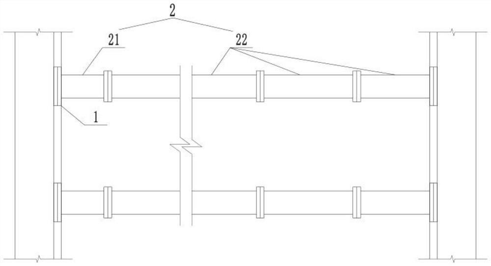
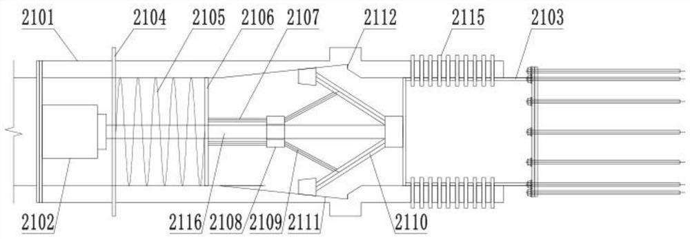
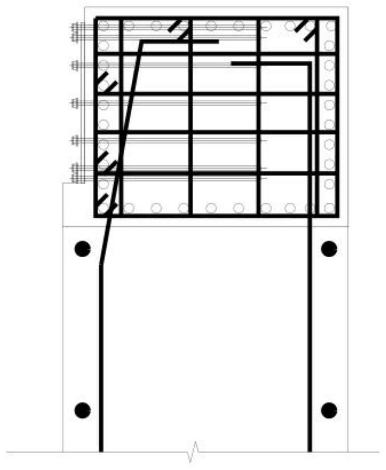
[0024] The purpose of the present invention is to provide a foundation pit steel supporting support structure that can withstand tensile force, which is used to replace the concrete support as the first horizontal support, saving construction costs and shortening the construction period.

[0025] In order to make the above objects, features and advantages of the present invention more comprehensible, the present invention will be further described in detail bel...


PUM

PropertyMeasurementUnit
Lengthaaaaaaaaaa
Outer diameteraaaaaaaaaa

Abstract

The invention discloses a foundation pit steel support supporting structure capable of bearing tension. The foundation pit steel support supporting structure comprises connecting joints and a supporting unit; the two connecting joints are used for being pre-buried in concrete on the two sides of a foundation pit correspondingly; the two ends of the supporting unit are fixedly connected with the two connecting joints through fasteners correspondingly; the supporting unit comprises at least one movable unit and a plurality of fixed units which are linearly distributed and sequentially connected through fasteners; and each movable unit comprises a first steel pipe, a hydraulic jack, a spring lock and a second steel pipe, wherein the hydraulic jack is fixed in the first steel pipe and provided with a telescopic shaft, one end of the second steel pipe is inserted in the first steel pipe, the telescopic shaft is fixedly connected with the second steel pipe, and the spring lock is located between the hydraulic jack and the second steel pipe. Compared with a concrete support, the steel support supporting structure has the beneficial effects that a steel support is more convenient to mount and dismount, the construction speed is higher, the construction period of the whole foundation pit is shortened, and the engineering cost is saved.

Description

technical field [0001] The invention relates to the technical field of underground structure engineering, in particular to a foundation pit steel supporting and supporting structure capable of bearing tension. Background technique [0002] For the construction of deep foundation pits, especially in the construction of open excavation foundation pits for subway stations, the first horizontal support is often made of reinforced concrete. Reinforced concrete support has the advantages of high rigidity, small deformation, firm joints, can bear both pressure and tension, and good overall stability. However, the construction process of reinforced concrete support is relatively complicated, and it takes a long time to wait for strength maintenance. It will be dismantled later The time is also longer. The installation and removal of steel supports are more convenient and the construction speed is faster. However, compared with reinforced concrete supports, steel supports have small...

Claims


Application Information

Patent Timeline
IPC IPC(8): E02D17/04E02D5/76
CPCE02D17/04E02D5/765
Inventor 丁华兴宋天田郭桃明黄际政黎心海吴旭贺梦龙谢俊吴永照林辉高龙华李炫松曾海勇赖志平
Owner SHENZHEN MUNICIPAL DESIGN & RES INST
Features
  • R&D
  • Intellectual Property
  • Life Sciences
  • Materials
  • Tech Scout
  • Unparalleled Data Quality
  • Higher Quality Content
  • 60% Fewer Hallucinations
Learn More