A connection structure between steel wire and transmission shaft, surgical robot and method

A connection structure and transmission shaft technology, applied in the field of medical equipment, can solve the problems of single transmission torque or push-pull force, complex structure, long time consumption, etc. of the transmission connection mechanism, and achieve the effects of labor-saving operation, convenient and fast process, and simple structure.

Active Publication Date: 2022-03-15
APEIRON SURGICAL CO LTD
View PDF9 Cites 0 Cited by
  • Summary
  • Abstract
  • Description
  • Claims
  • Application Information

AI Technical Summary

Problems solved by technology

[0005] The quick-connect and quick-disconnect separation ends of the transmission structure are mostly single active parts corresponding to single driven parts, and multi-active parts corresponding to multiple driven parts. Most of the mechanisms are connected separately, which takes a long time and is inefficient;
[0006] Most of the transmission connection mechanisms are single-transmission torque or push-pull force. When simultaneous transmission is required, most of them are multi-axis transmission and the structure is complex.

Method used


Image

  • A connection structure between steel wire and transmission shaft, surgical robot and method
  • A connection structure between steel wire and transmission shaft, surgical robot and method
  • A connection structure between steel wire and transmission shaft, surgical robot and method

Examples


Embodiment 2

[0061] This embodiment discloses a surgical robot, which is provided with the connection structure between the steel wire and the transmission shaft described in Embodiment 1, the transmission shaft is connected to the drive mechanism, and the drive mechanism can drive the transmission shaft to rotate around its own axis and to rotate along its own axis. For linear motion in the direction, the drive mechanism can be an existing drive mechanism for surgical robots, and its specific structure will not be described in detail here.

Embodiment 3

[0063] This embodiment discloses a method for connecting the transmission shaft and the steel wire connection structure described in Embodiment 1, such as Figure 6-Figure 9 shown, including the following steps:

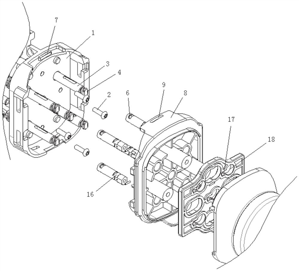
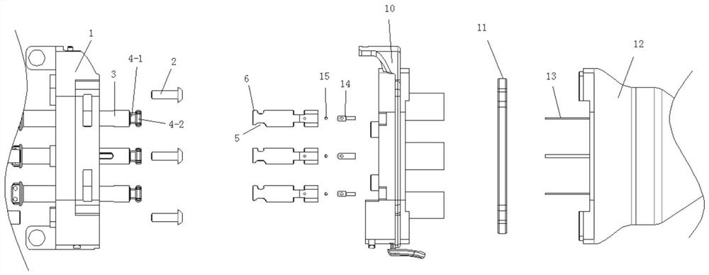
[0064] After passing the quick-connection shaft through the docking seat and dialing the card in advance, insert the connecting pin fixed with the steel wire into the end of the quick-connection shaft, and lock and fix it with the locking pin. Push the dial, so that the limiting portion of the quick-connect shaft enters the first hole. At this time, the quick-connect shaft is restricted by the first hole and cannot rotate around its own axis or move along its own axis.

[0065] Drive the structural movement composed of the docking seat, pipeline parts, dial card, steel wire rope, and quick-connect shaft, and move from top to bottom, so that the block of the transmission shaft is inserted into the groove, and the second block part extends into the arc-shaped plate Th...


PUM


Abstract

The invention relates to a connection structure between a steel wire and a transmission shaft, a surgical robot and a method thereof, including a base through which a plurality of transmission shafts pass, a block is provided at one end of the transmission shaft, and the transmission shaft is provided through the block and one end of the quick-connect shaft The card groove structure of the quick-connect shaft is detachably fixed, and the other end of the quick-connect shaft passes through the docking seat and is detachably fixed with the steel wire protruding from the pipe fitting. There is a Dial the card, the dial is provided with a through hole for the butt joint shaft to pass through, the through hole is composed of the first hole and the second hole, the movement of the quick connection shaft between the first hole and the second hole can realize fast The connection structure of the present invention can realize fast connection and disassembly by switching between the locking and loosening states of the connecting shaft and the dial card.

Description

technical field [0001] The invention relates to the technical field of medical devices, in particular to a connection structure between a steel wire and a transmission shaft, a surgical robot and a method. Background technique [0002] The statements herein merely provide background information related to the present invention and do not necessarily constitute prior art. [0003] At present, the steel wires and transmission shafts in the transmission mechanism of surgical robots need to be assembled in a one-to-one correspondence. The inventor found that the existing transmission mechanism of surgical robots has the following defects: [0004] After the transmission mechanism is installed, it cannot be quickly docked and disassembled; [0005] The quick-connect and quick-release split ends of the transmission structure are mostly single active parts corresponding to single driven parts, and multi-active parts corresponding to multiple driven parts. Most of the mechanisms ar...

Claims


Application Information

Patent Timeline
Patent Type & Authority Patents(China)
IPC IPC(8): F16C1/08F16C1/14F16D1/02A61B34/30
CPCF16C1/08F16C1/145F16D1/02A61B34/30F16M11/041A61B2017/00477F16D1/112F16C3/023F16C2226/62F16C2226/70F16C1/04F16C1/101F16C2316/10F16C2322/59F16L3/1075F16C2226/76
Inventor 袁平徐高峰范克顺
Owner APEIRON SURGICAL CO LTD
Why Eureka
Try Eureka