Miniature gas chromatograph for atmospheric pollution detection

A technology of micro-gas chromatography and protective shell, which is applied in the field of micro-gas chromatographs for air pollution detection. It can solve problems such as being vulnerable to bumps, exposed devices, and damaged devices, and achieves convenience in use, increased safety, and extended service life. Effect

Pending Publication Date: 2021-06-29
长兴萤火虫仪器仪表有限公司
View PDF1 Cites 1 Cited by
  • Summary
  • Abstract
  • Description
  • Claims
  • Application Information

AI Technical Summary

Problems solved by technology

[0006] The purpose of the present invention is: in order to solve the problem that the portable gas chromatograph uses universal wheels to move when it is moving, and it is inconvenient to pass...

Method used


Image

  • Miniature gas chromatograph for atmospheric pollution detection
  • Miniature gas chromatograph for atmospheric pollution detection
  • Miniature gas chromatograph for atmospheric pollution detection

Examples


Embodiment 1

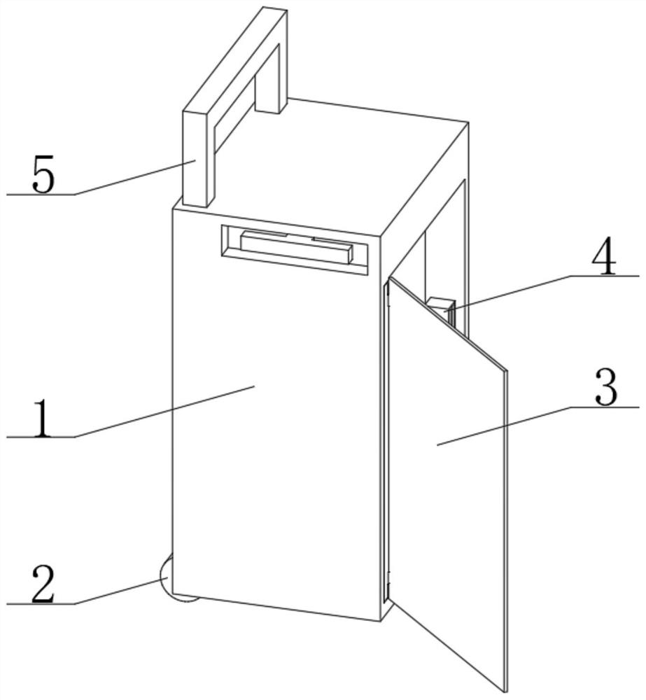
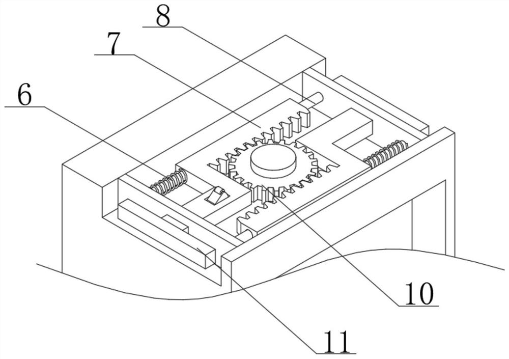
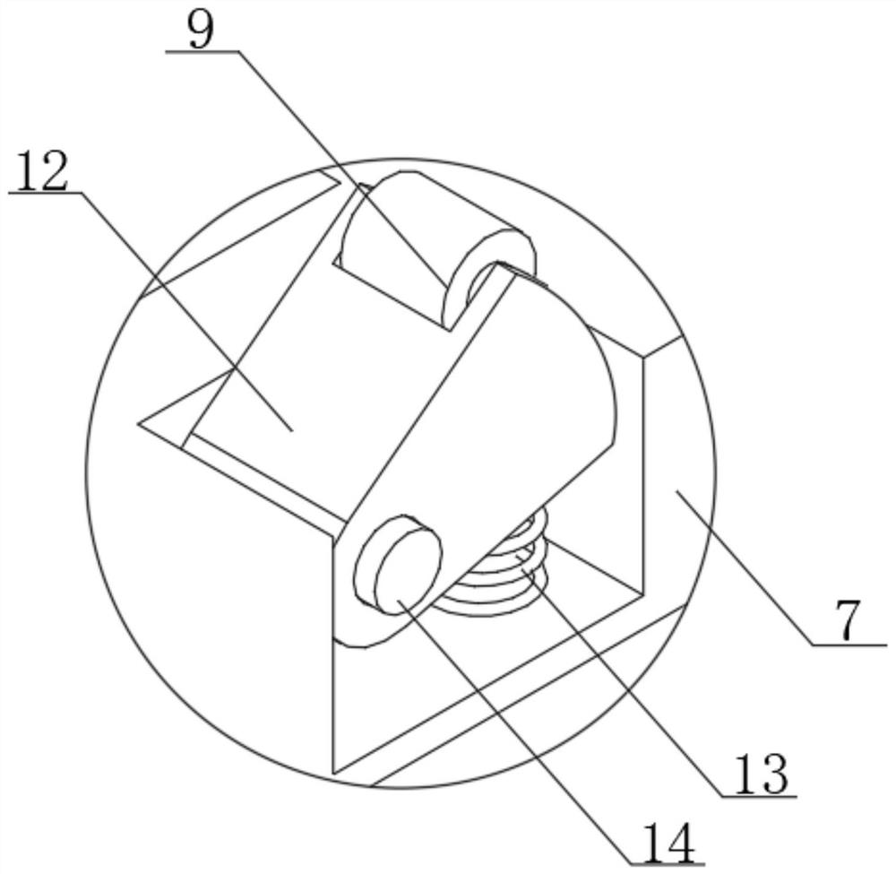
[0030] see Figure 1-3 , a miniature gas chromatograph for atmospheric pollution detection, comprising a protective shell 1, a roller 2 is movably connected to the bottom of one side of the protective shell 1, a telescopic rod 5 is movably connected to the inner side of the protective shell 1, and the top center of the protective shell 1 A rotating toothed plate 10 is rotatably connected at the top of the protective shell 1, and a guide rod 8 is fixedly connected to both sides of the top inner wall of the protective shell 1. One end of the guide rod 8 is sleeved with a rack 7, and the other end of the guide rod 8 is sleeved with a first compression spring. 6. The rack 7 and the protective shell 1 are movably connected by the first compression spring 6. One end of the rack 7 is fixedly connected with a pull rod 11, and one end of the rack 7 is fixedly connected with a second compression spring 13 inside. One end is fixedly connected with an installation shaft 14, the outer slee...

Embodiment 2

[0033] see figure 1 and 4 -6, This embodiment is further optimized on the basis of Embodiment 1. Specifically, one side of the protective shell 1 is provided with a movable groove 17, and one side of the movable groove 17 is fixedly connected to the third compression spring 18. One end of the three compression springs 18 is fixedly connected with the mounting plate 15 .

[0034] Specifically, the door panel 3 is fixedly connected to one side of the mounting plate 15 , and the mounting block 4 is fixedly connected to one side of the inner wall of the protective shell 1 .

[0035] Specifically, a mounting seat 20 is fixedly connected to one side of the door panel 3 , a clamping plate 19 is fixedly connected to one side of the mounting seat 20 , a hanging ring 22 is fixedly connected to the other side of the mounting seat 20 , and the center of the mounting seat 20 is fixedly connected There is a top plate 21 .

[0036] Specifically, one side of the mounting block 4 is provide...


PUM


Abstract

The invention discloses a miniature gas chromatograph for atmospheric pollution detection and relates to the technical field of meteorological chromatographs. The miniature gas chromatograph comprises a protective shell, wherein a roller is movably connected to the bottom of one side of the protective shell, a telescopic rod is movably connected to one side of the interior of the protective shell, and a rotating fluted disc is rotatably connected to the center of the top of the protective shell; guide rods are fixedly connected to two sides of an inner wall of the top of the protective shell, one end of each guide rod is sleeved with a rack, the other end of each guide rod is sleeved with a first compression spring, the racks are movably connected with the protective shell through the first compression springs, and one end of each rack is fixedly connected with a pull rod; and a second compression spring is fixedly connected into one end of the rack. According to the device, the door plate structure is arranged on one side of the protective shell, when the device is not used, the door plate can be closed, safety of the device is improved, the service life is prolonged, and when the device is used, the door plate can be opened to work normally.

Description

technical field [0001] The invention relates to the technical field of gas chromatographs, in particular to a micro gas chromatograph for air pollution detection. Background technique [0002] Gas chromatograph refers to a chromatographic analysis instrument that uses gas as a mobile phase. Its principle is mainly to use the differences in the boiling point, polarity and adsorption properties of substances to separate mixtures. The samples to be analyzed are gasified in the gasification chamber by inert gas (ie carrier gas, also known as mobile phase) is brought into the chromatographic column, the column contains liquid or solid stationary phase, and each component in the sample tends to form a distribution or adsorption equilibrium between the mobile phase and the stationary phase. In the flow of gas, the sample components are repeatedly distributed or adsorbed / desorbed during the movement. The components with high distribution concentration in the carrier gas flow out of ...

Claims


Application Information

Patent Timeline
IPC IPC(8): G01N30/02F16M3/00H05K5/02
CPCF16M3/00G01N30/02H05K5/0217
Inventor 王晶晶
Owner 长兴萤火虫仪器仪表有限公司
Why Eureka
Try Eureka