

Automatic fiber laying prepreg stiffness detection method
A technology of automatic wire laying and detection methods, applied in the direction of non-electric variable control, instruments, control/regulation systems, etc., can solve the problems of detection of prepreg tow performance, increase of test cost, and inability to directly apply, etc., to achieve detection speed The effects of fast, intuitive results, and simplified device structure
- Summary
- Abstract
- Description
- Claims
- Application Information
AI Technical Summary
Problems solved by technology
Method used
Image

Examples
Embodiment 1
[0039] This embodiment discloses a method for detecting the stiffness of an automatic laying prepreg, which specifically includes the following steps:
[0040] S1. Take out the 1000mm long prepreg tow from the cold storage, and place the prepreg tow in a constant temperature and humidity test chamber;
[0041] S2. After 60 minutes, take the prepreg tow out of the constant temperature and humidity test chamber, use scissors to cut 3 pieces of tow with a length of 60mm, and put the excess material back into the test chamber;
[0042] S3. Take out two pieces of prepreg tows and place them on the automatic laying test platform, adjust the position of the two pieces of tows so that the prepreg tows are completely covered;
[0043] S4. Set the laying pressure of the test platform to 100N, the laying speed to 10m / min, and the laying temperature to 35°C, start the automatic laying test platform, and realize the lamination of two pieces of prepreg tow;
[0044] S5. Place the third lay...
Embodiment 2
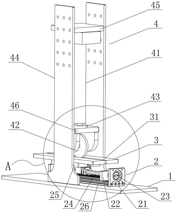
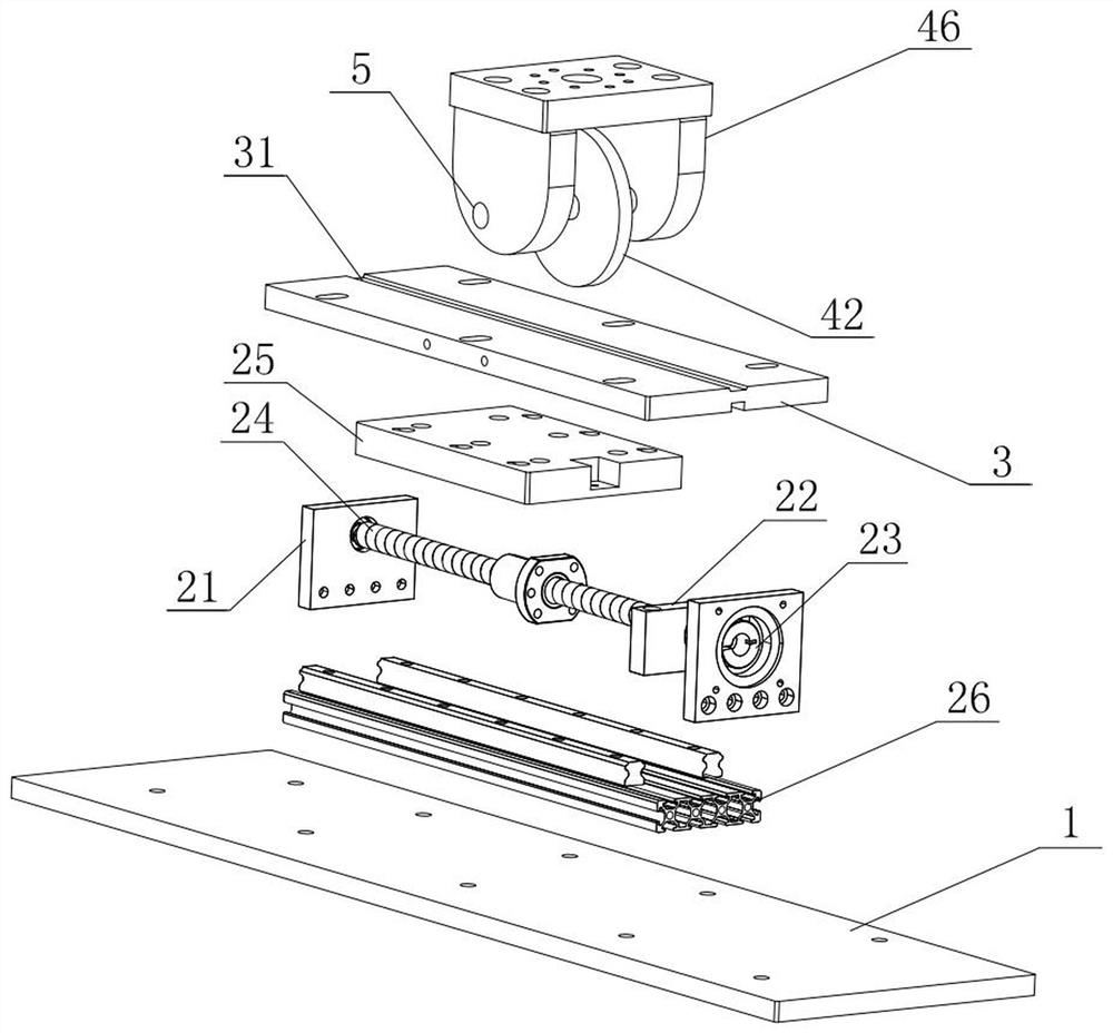
[0050] This embodiment discloses an automatic wire laying test platform, which is used to realize the laying and lamination of prepreg tows. Please refer to the accompanying drawings Figure 1-Figure 3 , the automatic laying test platform mainly includes a base 1, an SR80 double track ball screw slide table 2, a laying platform 3, a laying pressure control unit 4, a laying temperature control unit and a PLC controller; further, the The double track ball screw slide table 2 includes a screw support plate 21, a motor support plate 22, a servo motor 23, a ball screw 24, a working platform 25 and a line rail 26, a lead screw support plate 21, a motor support plate 22 and The line track 26 is arranged on the base 1, and limit switches are arranged at both ends of the line track 26, which are respectively the first limit switch and the second limit switch. The two limit switches are respectively connected with the PLC controller, and the limit switch It is used to prevent the entire...
Embodiment 3
[0055] This embodiment discloses a control method for an automatic wire laying test platform. The entire control process includes closed-loop control of laying pressure, closed-loop control of laying temperature, and closed-loop control of laying speed. When the automatic laying test platform is powered on, human The machine interface first sends the zero return command of the electric cylinder 41 and the double-rail ball screw slide table 2 to the PLC controller, and the PLC controller sends the zero return command to the electric cylinder driver and the servo motor driver respectively, and each driver receives the zero return command And execute the zero return operation, and judge whether the electric cylinder 41 and the double track ball screw slide table 2 return to zero through the corresponding limit switch in the whole process.
[0056] In this embodiment, laying pressure control and laying temperature control are carried out simultaneously, specifically:
[0057] Layi...
PUM
 Abstract
Description
Claims
Application Information