
Cooling jacket and motor

A cooling jacket and cooling channel technology, applied in cooling/ventilation devices, electrical components, electromechanical devices, etc., can solve the problems of high local pressure of the coolant, unfavorable coolant diffusion, large overpressure loss, etc., to reduce pressure loss, Avoid too much structural change and reduce the effect of local pressure drop

Pending Publication Date: 2021-06-29
SCHAEFFLER TECH AG & CO KG
View PDF0 Cites 0 Cited by
  • Summary
  • Abstract
  • Description
  • Claims
  • Application Information

AI Technical Summary

Problems solved by technology

[0005] The purpose of this application is to provide a cooling jacket and a motor including the cooling jacket, fundamentally solve the pressure drop of the total pressure loss of the current cooling channel up to 155mbar, which is not conducive to the diffusion of the coolant from the inlet joint to the outlet joint. The local pressure of the coolant near the joint area is high, and there is a technical problem of large overpressure loss in the spiral cooling channel

Method used


Image

  • Cooling jacket and motor
  • Cooling jacket and motor
  • Cooling jacket and motor

Examples


Embodiment Construction

[0035] The following description of the embodiments refers to the accompanying drawings to illustrate specific embodiments in which the invention may be practiced. The direction terms mentioned in the present invention, the terms "center", "longitudinal", "transverse", "length", "width", "thickness", "upper", "lower", "front", "back", The orientation or positional relationship indicated by "left", "right", "vertical", "horizontal", "top", "bottom", "inner", "outer", "clockwise", "counterclockwise" etc. is Based on the orientation or positional relationship shown in the drawings, it is only for the convenience of describing the present invention and simplifying the description, and does not indicate or imply that the referred device or element must have a specific orientation, be constructed and operated in a specific orientation, and therefore cannot be understood To limit the present invention. Therefore, the directional terms used are used to illustrate and understand the p...


PUM


Abstract

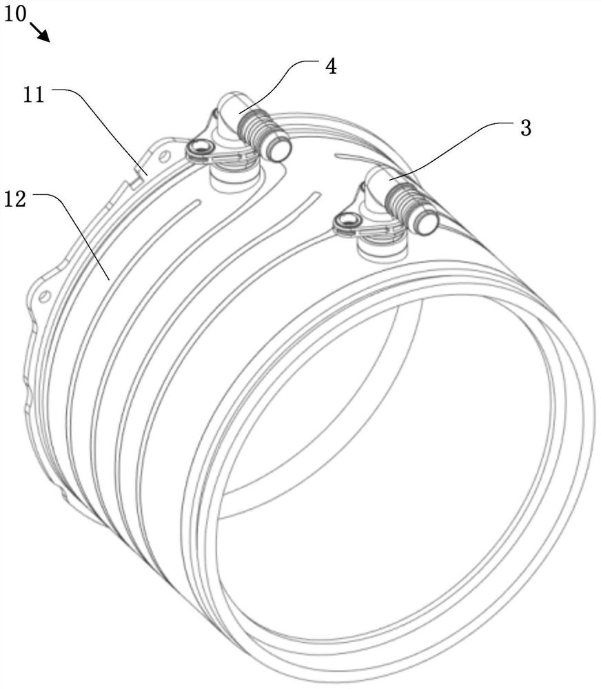
The invention discloses a cooling jacket and a motor comprising the same. The cooling jacket comprises an inlet joint, an outlet joint and a cooling channel; the inlet joint and the outlet joint are arranged on the peripheral surface of the cooling sleeve and are respectively positioned at two ends of the cooling jacket; the cooling channel is used for allowing a coolant to circulate; the cooling channel comprises a first cooling channel body and a second cooling channel body which are communicated with each other, the first cooling channel body and the second cooling channel body are different in shape and are arranged side by side in the axial direction of the cooling sleeve, the first cooling channel body is connected to the inlet connector, and the second cooling channel body is connected to the outlet connector. According to the cooling jacket, the cooling agent can be shunted after flowing into the cooling channel from the inlet connector, the local pressure drop of the cooling agent near the inlet area is remarkably reduced, the pressure loss of the cooling agent in the cooling channel is remarkably reduced, and the risk of overpressure loss does not exist in the cooling channel.

Description

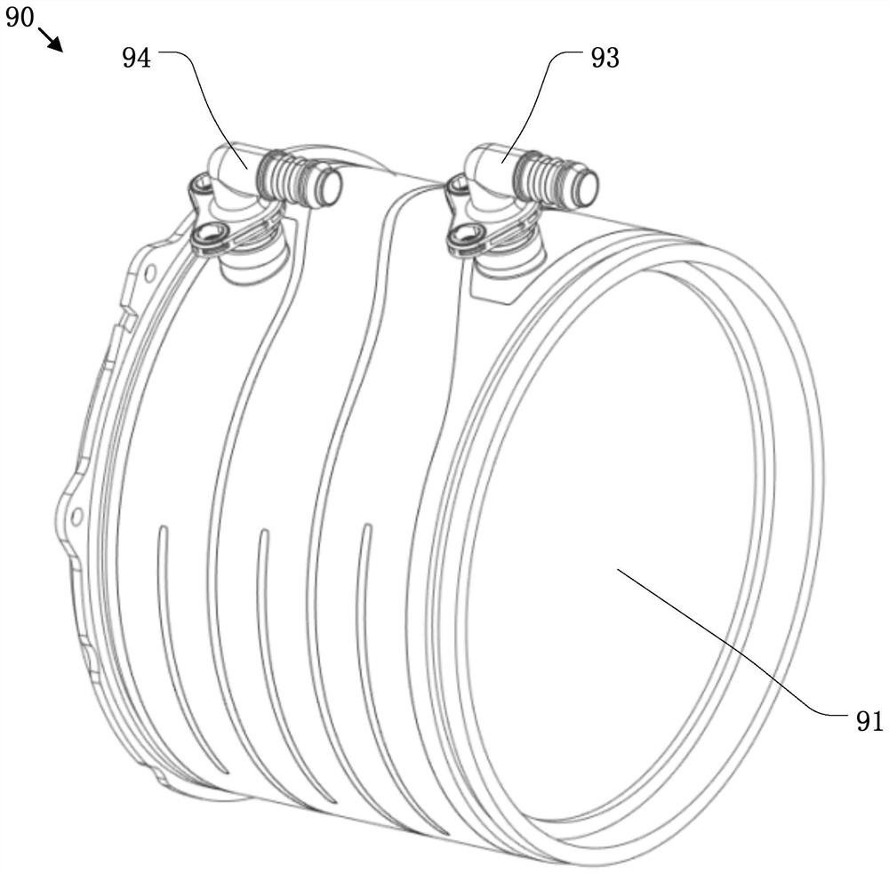
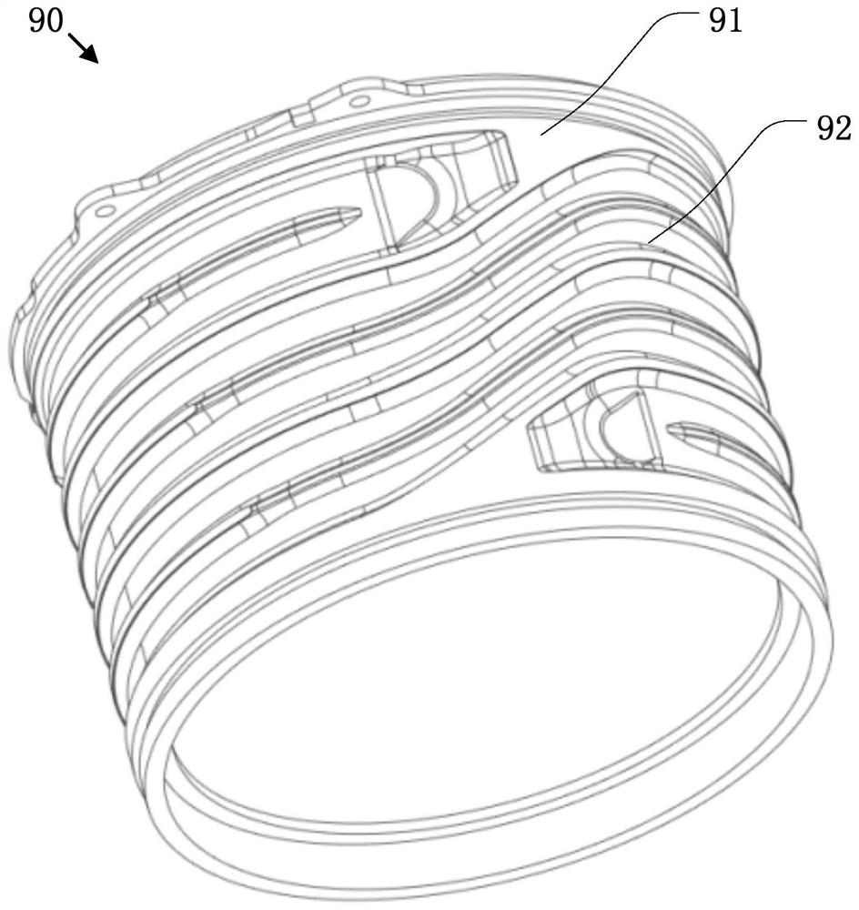
technical field [0001] The present application relates to the technical field of motor heat dissipation, in particular to a cooling jacket and a motor including the cooling jacket. Background technique [0002] In order to maintain the best performance of the motor and prolong the service life of the motor, the heat generated during its operation must be properly removed. In the prior art, a cold pipe flow channel is usually installed on the outside of this type of motor, and the coolant flowing in the pipe is used to exchange heat with the motor to achieve the purpose of removing waste heat from the motor. [0003] As permanent magnet synchronous motors with built-in magnets require continuous performance and higher power density, the design of cooling channels becomes more and more important. Such as figure 1 , figure 2 as shown, figure 1 It is a structural schematic diagram of a cooling jacket of an existing permanent magnet synchronous motor, figure 2 yes figure ...

Claims


Application Information

Patent Timeline
Patent Type & Authority Applications(China)
IPC IPC(8): H02K5/20H02K9/19
CPCH02K5/20H02K9/19
Inventor 胡亮宫宇
Owner SCHAEFFLER TECH AG & CO KG
Learn More