Sludge stirring device
A technology of stirring device and sludge, which is applied to mixers with rotary stirring devices, accessories of mixers, transportation and packaging, etc., can solve the problems of insufficient stirring of sludge, and achieve uniform and thorough stirring of sludge, convenient and easy replacement. The effect of stirring
- Summary
- Abstract
- Description
- Claims
- Application Information
AI Technical Summary
Problems solved by technology
Method used
Image


Examples
Embodiment 1
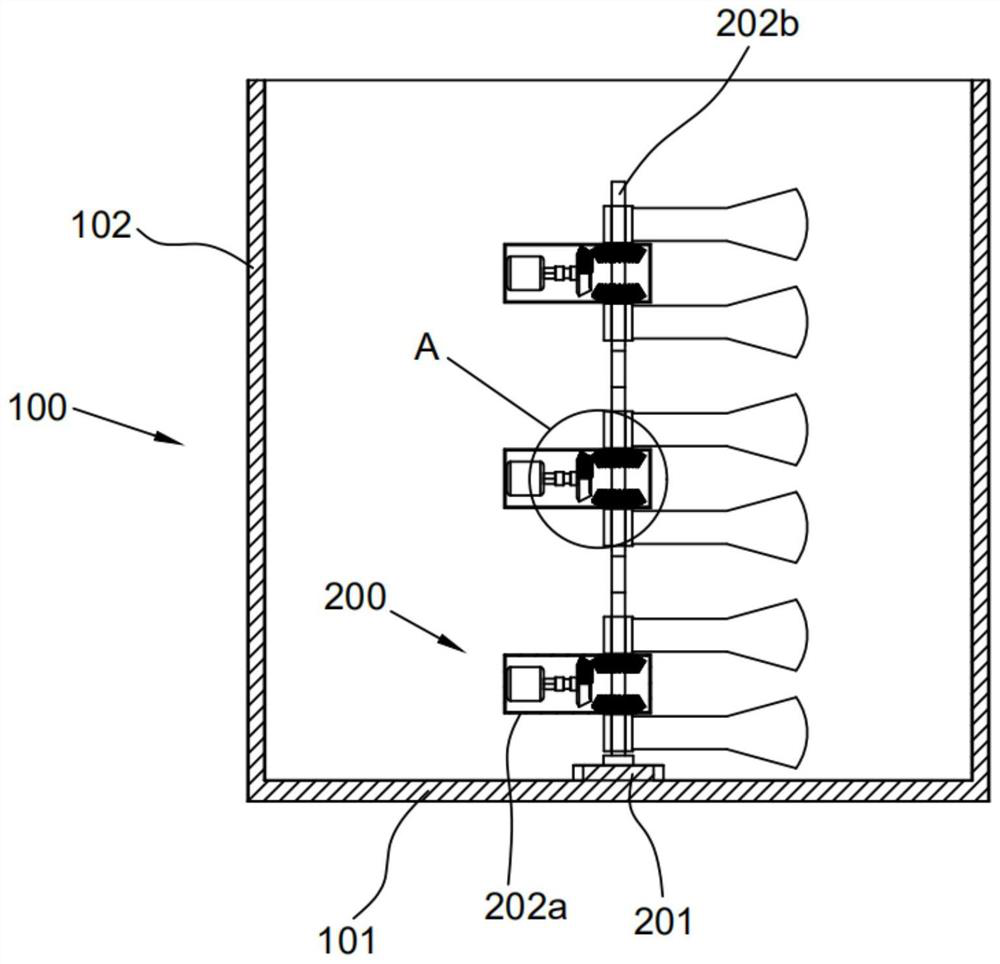
[0027] This embodiment provides a sludge stirring device, such as figure 1 with Figure 4 shown, including,
[0028] Stirring pool 100 includes a bucket bottom 101 and a cylinder wall 102 surrounding the top of the bucket bottom; A plurality of units 202 are vertically arranged and detachably connected. The stirring tank 100 is a circular cylinder, and the working module 200 is used for stirring the sludge and is arranged inside the stirring tank 100 .
[0029] The stirring unit 202 includes a housing 202a, and a rotating shaft 202b passes through the housing 202a. A coupling is arranged between two adjacent stirring units 202, and both ends of the coupling are inserted into the rotating shaft 202b for fixing. The housing 202a is used to protect the internal working components from the influence of sludge. The mixing units 202 are arranged vertically and connected up and down by couplings. This method is easy to install and disassemble, and the individual mixing units 202 c...
Embodiment 2
[0034] This embodiment is different from the previous embodiment in that, as Figure 1-3 as shown,
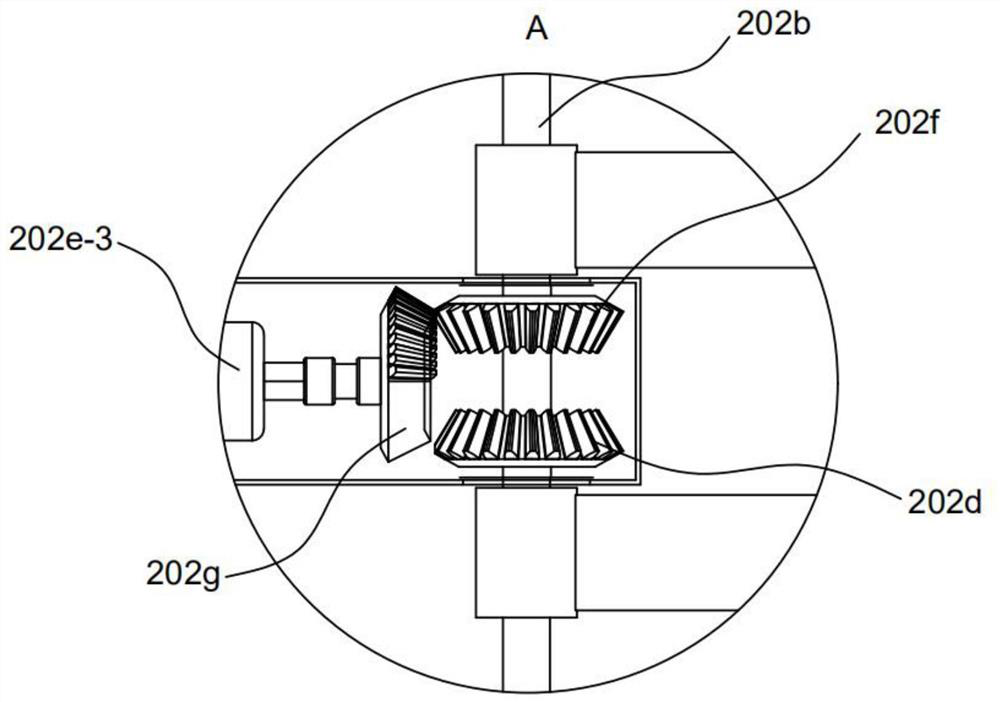
[0035] A first bevel gear 202d is sheathed on the rotating shaft 202b, and a drive module 202e is arranged on the side of the first bevel gear 202d. 202d and the third bevel gear 202f are meshed with a half-tooth bevel gear 202g, the half-tooth bevel gear 202g periodically drives the first bevel gear 202d and the third bevel gear 202f to rotate, and the side of the half-tooth bevel gear 202g is provided with a second driving motor 202e -3. The drive shaft of the second driving motor 202e-3 is inserted into the center of the half-tooth bevel gear 202g and fixed thereto. The gears 202f mesh alternately.
[0036] The part of the rotating shaft 202b outside the housing 202a is connected with a stirring blade 202c, and the stirring blade 202c is symmetrically arranged on the outside of the first bevel gear 202d and the third bevel gear 202f. Spiral blades, etc., are used to stir...
Embodiment 3
[0039] This embodiment is different from the previous embodiment in that, as Figure 5-6 as shown,
[0040] The end of the rotating shaft 202b is provided with a sliding groove 202b-1 in the axial direction. The sliding groove 202b-1 is opened from the end surface of the rotating shaft 202b to the inside of the rotating shaft. The receiving groove 202b-2 opened in the circumferential direction, the receiving groove 202b-2 is also connected with the locking groove 202b-3 perpendicular to the sliding groove 202b-1, the receiving groove 202b-2 is provided with a spring 202b-4, the receiving groove 202b- 2 The shape corresponds to the shape of the spring 202b-4, and is used to accommodate the spring 202b-4. The distance between the locking groove 202b-3 and the sliding groove 202b-1 is 90°, and the locking groove 202b-3 is set inside the rotating shaft 202b. The shape of the groove 202b-3 is the same as that of the sliding groove 202b-1, which is a square groove; the end of the s...
PUM
 Abstract
Description
Claims
Application Information
 - R&D
- Intellectual Property
- Life Sciences
- Materials
- Tech Scout
- Unparalleled Data Quality
- Higher Quality Content
- 60% Fewer Hallucinations
Browse by: Latest US Patents, China's latest patents, Technical Efficacy Thesaurus, Application Domain, Technology Topic, Popular Technical Reports.
© 2025 PatSnap. All rights reserved.Legal|Privacy policy|Modern Slavery Act Transparency Statement|Sitemap|About US| Contact US: help@patsnap.com