
Method for machining part by using laser melting forming device

A technology of laser melting and laser cladding, applied in the direction of additive processing, additive manufacturing, etc., can solve the problems that parts cannot achieve self-healing effect, and the parameters of defocus amount cannot be determined, so as to achieve uniform structure and performance, and promote Consistent, fast self-healing effect

Active Publication Date: 2021-07-02
AECC SHANGHAI COMML AIRCRAFT ENGINE MFG CO LTD +1
View PDF7 Cites 2 Cited by
  • Summary
  • Abstract
  • Description
  • Claims
  • Application Information

AI Technical Summary

Problems solved by technology

[0004] The technical problem to be solved by the present invention is to overcome the defect that the parameters of the defocus amount cannot be determined in the process of generating parts by laser melting deposition technology in the prior art, resulting in the inability of the processed parts to achieve the best self-healing effect, and to provide a laser Method for processing parts by melting forming device

Method used

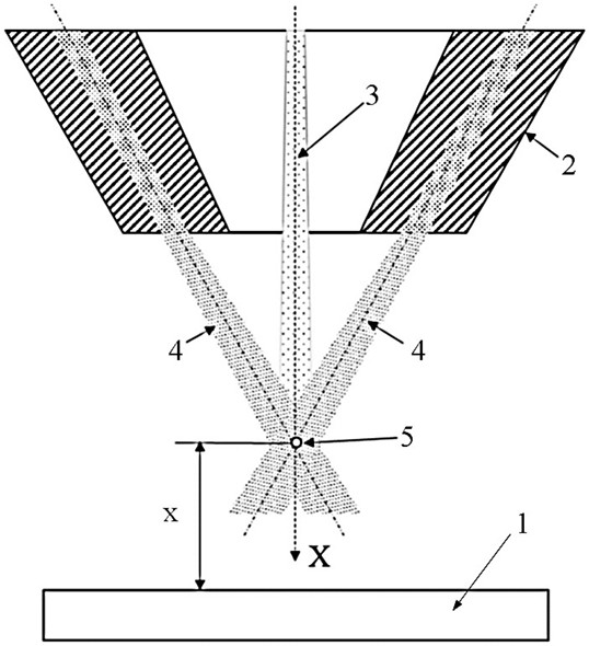

Image

  • Method for machining part by using laser melting forming device
  • Method for machining part by using laser melting forming device
  • Method for machining part by using laser melting forming device

Examples


Embodiment Construction

[0048] In the following, the present invention will be more clearly and completely described by means of an embodiment in conjunction with the accompanying drawings, but the present invention is not limited to the scope of the embodiment.

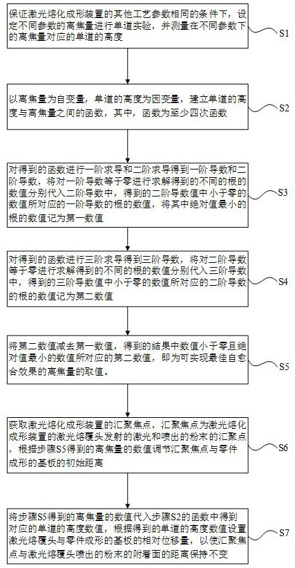
[0049] Such as figure 1 As shown, it is a method for processing parts using a laser melting forming device disclosed in this embodiment, which includes the following steps:

[0050] S1. Under the condition that the other process parameters of the laser melting forming device are the same, set the defocus amount of different parameters to conduct a single-track experiment, and measure the height of the single-track corresponding to the defocus amount of different parameters;

[0051] S2. Using the defocus amount as the independent variable and the height of the single track as the dependent variable, establish a function between the height of the single track and the defocus amount, wherein the function is at least a quartic function;

[00...


PUM


Abstract

The invention discloses a method for machining a part by using a laser melting forming device. The method comprises the following steps that a function relation between the single-channel height and the defocusing amount is established; deriving is carried out on an obtained function, different roots obtained by solving that a first derivative is equal to zero are respectively substituted into a second derivative, numerical values of the roots of the first derivative corresponding to numerical values smaller than zero in the numerical values of the second derivative are obtained, and the numerical value of the root with the minimum absolute value is recorded as a first numerical value; numerical values of different roots obtained by solving that the second derivative is equal to zero are respectively substituted into a third derivative, and numerical values of the roots of the second derivative corresponding to numerical values smaller than zero in the numerical values of the third derivative are recorded as second numerical values; and the first numerical value is subtracted from the second numerical values, and the second numerical value corresponding to the numerical value which is smaller than zero and has the minimum absolute value in the result is the value of the defocusing amount capable of realizing the optimal self-healing effect. According to the method, optimal defocusing amount parameters can be obtained.

Description

technical field [0001] The invention relates to a method for processing parts by using a laser melting forming device. Background technique [0002] Laser melting deposition technology, as one of the typical metal additive manufacturing technologies, is based on the principle of "discrete + accumulation", slices the three-dimensional model of the part, discretizes it into two-dimensional information and performs motion path planning, and uses laser as the heat source to form on the substrate. The melting pool, combined with synchronous powder delivery, realizes the rapid melting and solidification of powder in the melting pool, and deposits layer by layer to complete the three-dimensional solid forming of parts. This technology has the characteristics of high flexibility, short cycle time, high performance and near-net shape without dies. It is widely used in the forming of large-scale metal components in aerospace and the repair of high-value parts. [0003] During the par...

Claims


Application Information

Patent Timeline
Patent Type & Authority Applications(China)
IPC IPC(8): B22F10/28B22F10/36B22F10/85B33Y10/00B33Y50/02
CPCB33Y10/00B33Y50/02Y02P10/25B22F10/366B22F2998/10B22F10/31B22F10/28B22F10/85
Inventor 付鑫雷力明付俊石磊焦宗戈王悦
Owner AECC SHANGHAI COMML AIRCRAFT ENGINE MFG CO LTD
Learn More