Cutting and edging equipment for high-end equipment manufacturing

An edge grinding equipment and equipment technology, applied in other manufacturing equipment/tools, manufacturing tools and other directions, can solve the problems of cumbersome fixing methods, inability to guarantee workpiece grinding efficiency, high cost, low labor intensity, reduced labor intensity, and simple operation. Effect

Active Publication Date: 2021-07-02
东营华洋金属制品有限公司
View PDF6 Cites 4 Cited by
  • Summary
  • Abstract
  • Description
  • Claims
  • Application Information

AI Technical Summary

Problems solved by technology

[0006] In order to overcome the disadvantages that the existing grinding equipment fixes the workpiece in a troublesome way, the grinding efficiency of the workpiece cannot be guaranteed, the workpiece needs to be used in conjunction with other cutting equipment, and its c

Method used


Image

  • Cutting and edging equipment for high-end equipment manufacturing
  • Cutting and edging equipment for high-end equipment manufacturing
  • Cutting and edging equipment for high-end equipment manufacturing

Examples


Example Embodiment

[0029] Example 1

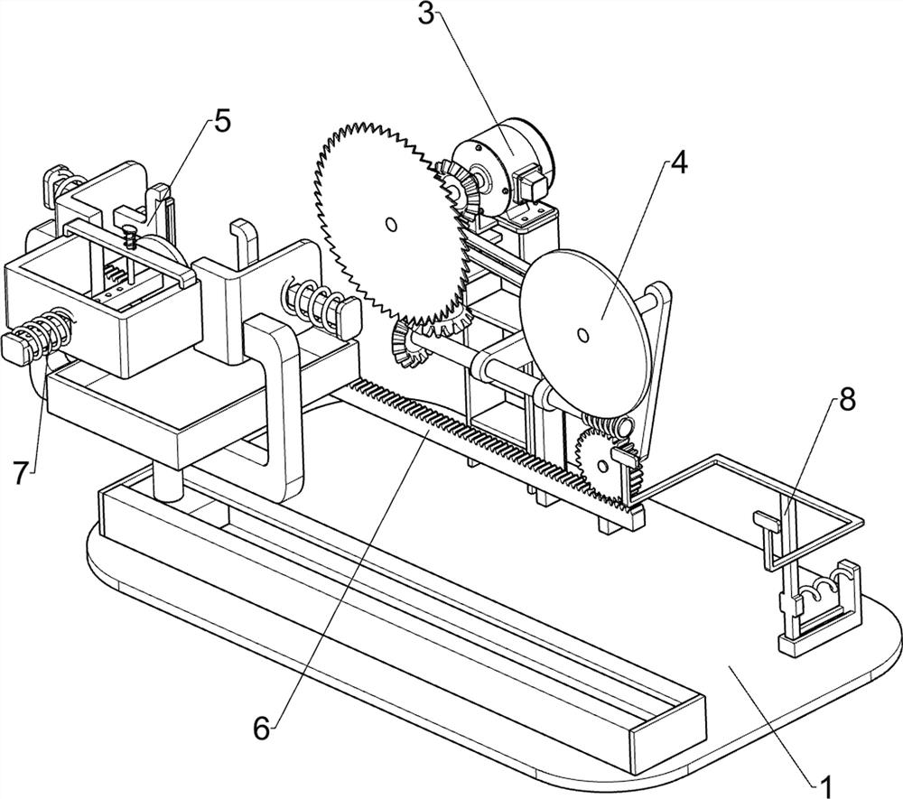
[0030] A cutting and edging equipment manufactured by high-end equipment, such as Figure 1 to Figure 4 As shown, it includes a base plate 1, a support frame 2, a cutting mechanism 3, a grinding mechanism 4 and a clamping mechanism 5. The top front side of the base plate 1 is connected with a support frame 2, and the top of the base plate 1 is equipped with a cutting mechanism 3. The cutting mechanism 3 A grinding mechanism 4 is connected with the support frame 2 , and the grinding mechanism 4 is connected to the cutting mechanism 3 in transmission, and a clamping mechanism 5 is installed on the rear side of the top of the bottom plate 1 .

[0031] The cutting mechanism 3 includes a base 31, a servo motor 32, a rotating shaft 33 and a two-way saw blade 34. The front side of the top of the base plate 1 is connected with a base 31. A servo motor 32 is installed on the base 31. The output shaft of the servo motor 32 is connected with a rotating shaft 33. , the...

Example Embodiment

[0035] Example 2

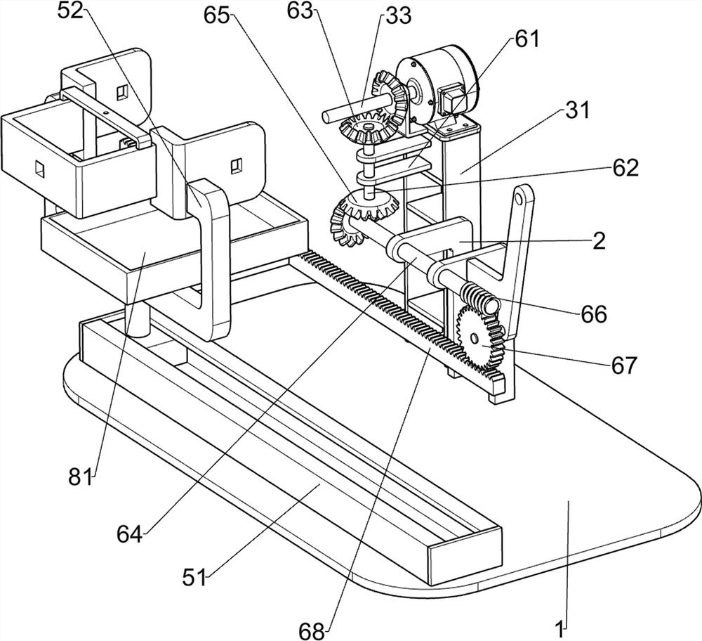
[0036] On the basis of Example 1, such as Figure 5As shown, a moving mechanism 6 is also included, and the moving mechanism 6 includes a fixed frame 61, a second connecting shaft 62, a first bevel gear set 63, a third connecting shaft 64, a second bevel gear set 65, a worm screw 66, and a worm wheel 67 With the rack frame 68, the rear side top of the base 31 is connected with a fixed mount 61, and the fixed mount 61 is connected with a second connecting shaft 62 in a rotational manner, and a first cone is installed between the top of the second connecting shaft 62 and the rotating shaft 33. Gear set 63, the middle part of support frame 2 is connected with the third connecting shaft 64 rotationally, the second bevel gear set 65 is connected between the right end of the third connecting shaft 64 and the bottom end of the second connecting shaft 62, the third connecting The left end of shaft 64 is equipped with worm screw 66, and the rear side bottom of suppo...

Example Embodiment

[0038] Example 3

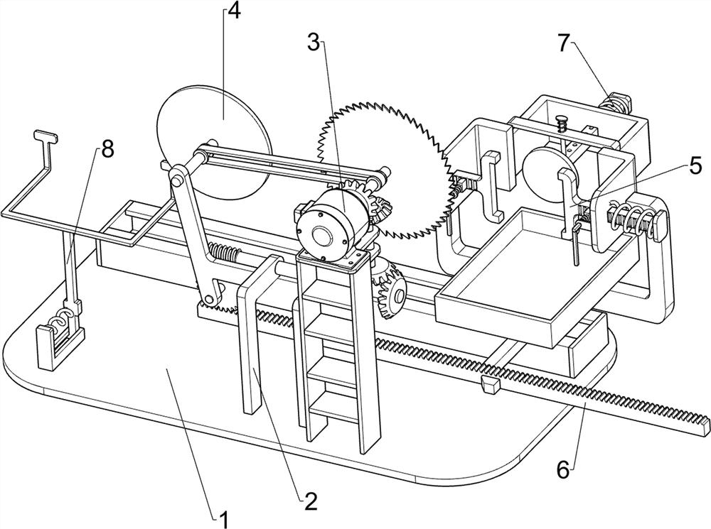
[0039] On the basis of Example 2, such as Figure 4 to Figure 7 As shown, feed mechanism 7 is also included, and feed mechanism 7 comprises hole guide rod 71, the 3rd spring 72, guide post 73 and the 4th spring 74, and the upper rear side of mounting frame 52 is slidably connected with belt The hole guide rod 71 is connected with the third spring 72 between the rear end of the hole guide rod 71 and the top rear side of the mounting frame 52, and the third spring 72 is sleeved on the outside of the hole guide rod 71, and the top of the mounting frame 52 A guide post 73 is slidably connected, and the guide post 73 is engaged with the guide rod 71 with a hole. A fourth spring 74 is connected between the top of the guide post 73 and the top of the installation frame 52 .

[0040] The workpiece can be positioned through the guide rod 71 with a hole to avoid moving backward on the mounting frame 52 when the workpiece is cut. When it is necessary to adjust the cut...


PUM


Abstract

The invention relates to cutting and edging equipment, in particular to cutting and edging equipment for high-end equipment manufacturing. According to the cutting and edge grinding equipment for high-end equipment manufacturing, the fixing mode of a workpiece is simple, the workpiece grinding efficiency can be improved, and the workpiece can be cut. In order to solve the technical problem, the invention provides the cutting and edging equipment for high-end equipment manufacturing. The cutting and edging equipment comprises a bottom plate, a cutting mechanism, a grinding mechanism and a clamping mechanism, wherein the top of the bottom plate is connected with a supporting frame; the cutting mechanism is mounted at one side of the top of the bottom plate; the grinding mechanism is connected between the cutting mechanism and the supporting frame; and the clamping mechanism is mounted at the other side of the top of the bottom plate. According to the cutting and edging equipment, by means of the cutting mechanism, the grinding mechanism and the clamping mechanism, the workpiece can be integrally cut and ground, the mounting frame only needs to be manually pushed to move, operation is easy, and the labor intensity is low.

Description

technical field [0001] The invention relates to a cutting and edging equipment, in particular to a cutting and edging equipment manufactured by high-end equipment. Background technique [0002] The high-end equipment manufacturing industry refers to the high-end field of the equipment manufacturing industry. "High-end" is mainly manifested in three aspects: first, high-tech content, manifested as intensive knowledge and technology, reflecting the inheritance of multi-disciplinary and multi-field high-precision technology; Second, it is at the high end of the value chain and has the characteristics of high added value; third, it occupies a core position in the industrial chain, and its development level determines the overall competitiveness of the industrial chain. [0003] Patent application CN110293092A, published on 2019.10.01, discloses a grinding device for high-end equipment manufacturing, including a housing, a bearing plate is fixedly connected to the bottom side wal...

Claims


Application Information

Patent Timeline
IPC IPC(8): B23P23/04
CPCB23P23/04
Inventor 李燕子
Owner 东营华洋金属制品有限公司
Why Eureka
Try Eureka