Method, device, system and electronic device for detecting crankshaft position of hybrid vehicle

A crankshaft position and hybrid vehicle technology, applied in the computer field, can solve problems such as large errors in rotational speed and position, and inability to determine the position of the crankshaft after it stops.

Active Publication Date: 2022-07-15
WEICHAI POWER CO LTD +1
View PDF4 Cites 0 Cited by
  • Summary
  • Abstract
  • Description
  • Claims
  • Application Information

AI Technical Summary

Problems solved by technology

[0003] Since the frequency and amplitude of the crankshaft speed sensor signal change with the speed, when the engine is about to shut down, the crankshaft speed decreases, and the frequency and amplitude of the output signal of the crankshaft sensor decrease rapidly at this time, and the speed and position errors are large, so it is impossible to determine the stop Position of the crankshaft after the engine is turned off

Method used


Image

  • Method, device, system and electronic device for detecting crankshaft position of hybrid vehicle
  • Method, device, system and electronic device for detecting crankshaft position of hybrid vehicle
  • Method, device, system and electronic device for detecting crankshaft position of hybrid vehicle

Examples


Embodiment approach

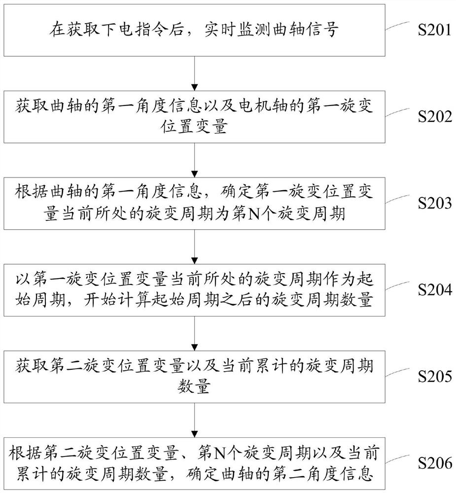
[0071] Optionally, in another embodiment of the present application, an implementation manner of step S203 includes:

[0072] According to the first angle information of the crankshaft and the rotation angle of the crankshaft every time one resolver cycle passes, it is determined that the resolver cycle in which the first resolver position variable is currently located is the Nth resolver cycle.

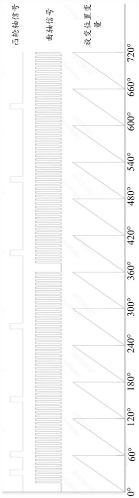
[0073] Continuing the above example, the angle of rotation of the crankshaft after each revolution cycle can be obtained by calculation: in one working cycle of the engine, the crankshaft needs to rotate twice, and 12 revolution cycles can be obtained, that is, 360*2 / 12=60°, then when obtaining the first angle information, such as 132°, directly divide the first angle information by the angle 60° of crankshaft rotation every time a resolver cycle passes, and obtain the first angle information after 2 The resolver period, and the result of 12° more, that is, the resolver period in wh...


PUM


Abstract

The present application provides a method, device, system and electronic equipment for detecting the crankshaft position of a hybrid vehicle, and a method for detecting the crankshaft position of a hybrid vehicle, by monitoring the current speed of the crankshaft in real time after obtaining a power-off command; The first angle information and the first resolver position variable of the motor shaft; then, according to the first angle information of the crankshaft, it is determined that the current resolver cycle of the first resolver position variable is the Nth resolver cycle; The current resolver cycle of the first resolver position variable is used as the start cycle, and the number of resolver cycles after the start cycle starts to be calculated; the second resolver position variable and the current accumulated number of resolver cycles are obtained; The variable position variable, the Nth resolver cycle and the current accumulated number of resolver cycles determine the angle information of the crankshaft when the engine stops rotating. Thereby, the purpose of accurately determining the position of the crankshaft after stopping when the engine is stopped and turned off is achieved.

Description

technical field [0001] The present application relates to the field of computer technology, and in particular, to a method, device, system and electronic device for detecting the position of a crankshaft of a hybrid vehicle. Background technique [0002] At present, when the engine is synchronizing, it is necessary to identify the missing tooth position of the crankshaft and the multi-tooth position of the camshaft, so at least one revolution of the crankshaft is required to synchronize. [0003] Since the frequency and amplitude of the crankshaft speed sensor signal change with the speed, when the engine is about to be shut down, the crankshaft speed decreases. At this time, the frequency and amplitude of the output signal of the crankshaft sensor decrease rapidly, and the speed and position errors are large, so it is impossible to determine the stop The position after the crankshaft is stopped when the engine is turned off. SUMMARY OF THE INVENTION [0004] In view of t...

Claims


Application Information

Patent Timeline
Patent Type & Authority Patents(China)
IPC IPC(8): B60W40/12B60W20/00
CPCB60W40/12B60W20/00B60W2510/06
Inventor 王裕鹏韩福强王涛李忠银
Owner WEICHAI POWER CO LTD
Why Eureka
Try Eureka