Check patentability & draft patents in minutes with Patsnap Eureka AI!

A thermal imaging target

A thermal imaging and heat technology, applied to targets, offensive equipment, etc., can solve the problems of inability to calibrate and test thermal imaging sights, not to mention measuring and reflecting shooting results, and no easy-to-use target paper, etc. Convenience, convenience, economy, hidden fire safety hazards, no effect of open fire safety hazards

Active Publication Date: 2022-08-05
SHENZHEN GONGFENXIANG NETWORK TECH CO LTD
View PDF0 Cites 0 Cited by
  • Summary
  • Abstract
  • Description
  • Claims
  • Application Information

AI Technical Summary

Problems solved by technology

[0003] With the development of technology, thermal imaging sights are especially popular in hunting and military activities because they can find and hit targets in dark environments. However, as a kind of sights, thermal imaging sights are not as simple as Easy-to-use target paper, because the thermal imaging sight cannot see the color or color ring on the ordinary target paper, the thermal imaging sight can only see the temperature difference on the target paper, and the ordinary target paper has the same material, the color on the target paper There is almost no temperature difference between the ring or bull ring, which is almost invisible to the thermal imaging sight, so that it cannot realize its function of calibrating and verifying the thermal imaging sight
In the use of the existing technology, people realize the calibration and inspection functions of thermal imaging sights by means of adapting measures to local conditions. Some use electric heating, some use fire to heat small iron blocks to make bullseye, and some use metal tape skin and then exposed to the sun to obtain the temperature difference on the target. Although these methods can be used, they are either not simple and easy to use, or the cost is not cheap so that it is not economical and practical, or because the materials need to be reused, they need to be reused after use. Take a long way to recover, such as electric heating and iron blocks, etc., or because the temperature of the target cannot last long enough, it needs to be reheated, let alone accurately measure and reflect the shooting results

Method used


Image

  • A thermal imaging target
  • A thermal imaging target
  • A thermal imaging target

Examples


Embodiment Construction

[0031] The following describes in detail the embodiments of the present invention, examples of which are illustrated in the accompanying drawings, wherein the same or similar reference numerals refer to the same or similar elements or elements having the same or similar functions throughout. The embodiments described below with reference to the accompanying drawings are exemplary, and are intended to explain the present invention and should not be construed as limiting the present invention.

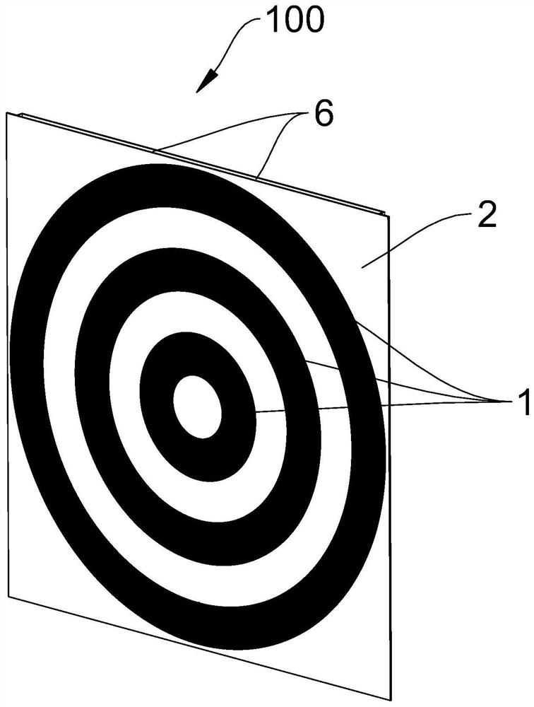
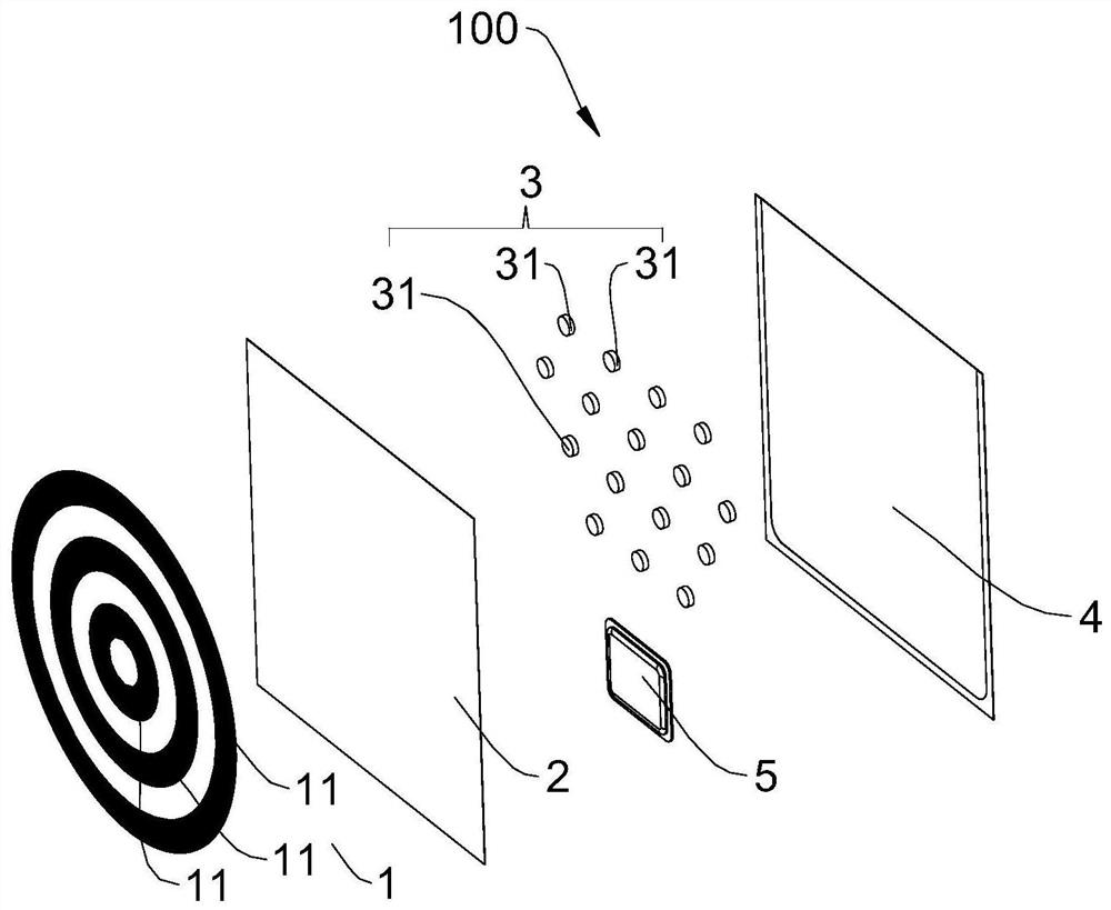
[0032] Please refer to Figure 1 to Figure 2 , which is a thermal imaging target 100 provided by the present invention, which is used for shooting training, and includes a heat insulation layer 1 , a heat conduction layer 2 , a flow guide layer 3 , a bottom layer 4 and a self-heating pack 5 .

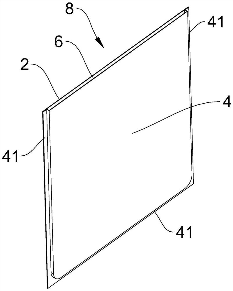
[0033] like image 3 As shown, the thermally conductive layer 2 of the present invention is hermetically connected to the edge of the bottom layer 4 and has an opening 6 at the top end to form a ...


PUM


Abstract

The invention provides a thermal imaging target for shooting training, comprising a heat insulation layer, a heat conduction layer, a flow guiding layer, a bottom layer and a self-heating package; the heat conduction layer is sealed with the edge of the bottom layer, and is opened at the top to form a pocket The self-heating package is placed in the pocket, and the self-heating material is arranged in the self-heating package to generate heat; the guide layer is supported between the heat-conducting layer and the bottom layer in the pocket and forms a cross-connected heat dissipation cavity the heat-insulating layer is attached to the outer surface of the heat-conducting layer; the heat-conducting performance of the heat-insulating layer is lower than that of the heat-conducting layer, so that the heat During conduction, a temperature difference is formed between the thermally conductive layer and the thermally insulating layer. The thermal imaging target of the invention has a temperature difference that lasts long enough to be clearly seen by the thermal imaging sight, has simple structure, convenient use and low cost, and is suitable for popularization and application.

Description

technical field [0001] The invention relates to a target for shooting and aiming, in particular to a thermal imaging target suitable for shooting with a thermal imaging sight. Background technique [0002] Since its invention, the sight has been widely used in competitions, hunting and military activities because of its accuracy, and the target, or target paper, is an important tool for the calibration and inspection of the sight during use. The paper is easy to use, inexpensive to manufacture, and the rings on the target paper have standard diameters and sizes, which can accurately measure and reflect shooting results. [0003] With the development of technology, thermal imaging sights are particularly loved in hunting and military activities because they can find and hit targets in dark environments. However, as a type of sight, thermal imaging sights are not as simple as Easy-to-use target paper, because the thermal imaging sight cannot see the color or color ring on the...

Claims


Application Information

Patent Timeline
IPC IPC(8): F41J1/01
CPCF41J1/01F41J2/02F41J5/24
Inventor 吕良
Owner SHENZHEN GONGFENXIANG NETWORK TECH CO LTD
Features
  • R&D
  • Intellectual Property
  • Life Sciences
  • Materials
  • Tech Scout
  • Unparalleled Data Quality
  • Higher Quality Content
  • 60% Fewer Hallucinations
Learn More