Antenna and remote controller
An antenna and reflector technology, applied in the field of communication, can solve the problem of difficult to meet the multi-band resonance wave reception and transmission, and achieve the effect of reducing negative effects, ensuring reliable communication, and good directionality
- Summary
- Abstract
- Description
- Claims
- Application Information
AI Technical Summary
Problems solved by technology
Method used
Image

Examples
Embodiment
[0065] Refer below Figure 1-Figure 9 A remote controller of a specific embodiment of the present invention is described.
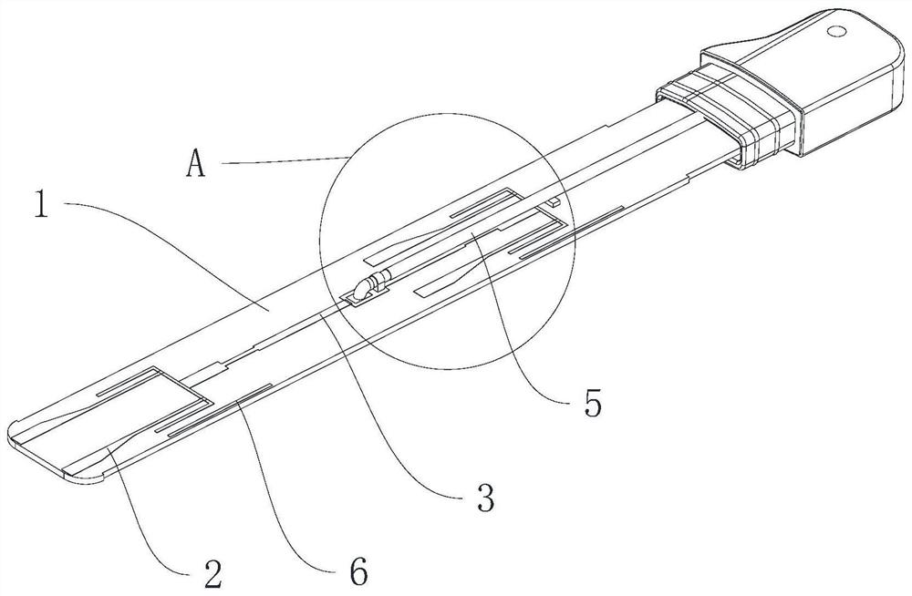
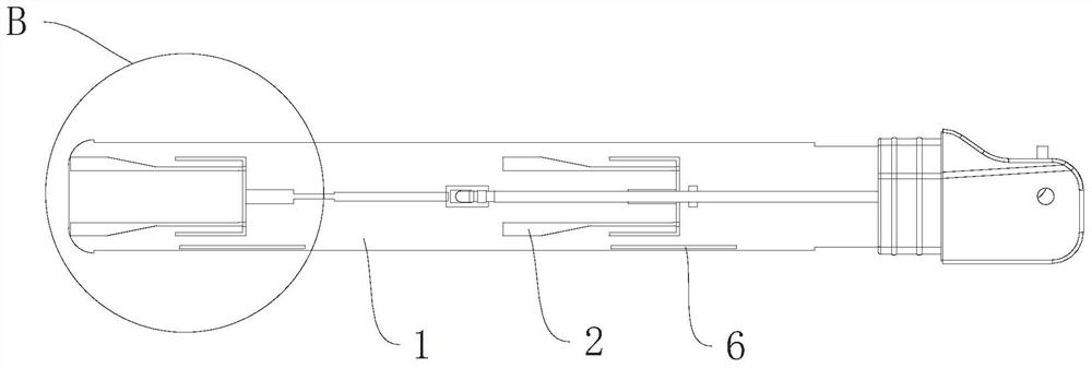
[0066] The remote controller of this embodiment includes a main body 8 , a mounting part 9 and the aforementioned antenna. The mounting part 9 is rotatably connected to the body 8 . The antenna is provided in the mounting part 9 .
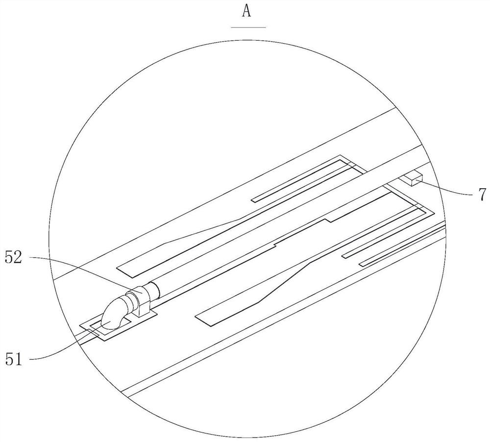
[0067] The antenna includes a substrate 1 , a vibrator group, a connecting piece 3 , a coaxial line 5 , a limiting piece 7 and a reflector 6 .
[0068]The vibrator group includes a plurality of first vibrator parts 2 distributed along the length direction of the substrate 1 and a plurality of second vibrator parts 4 distributed along the length direction of the substrate 1. The first vibrator parts 2 and the second vibrator parts 4 are arranged on two sides of the substrate 1. side. The first oscillator part 2 includes a first connecting oscillator arm 21 , a first high-frequency oscillator arm 22 and a first low-frequency...
PUM
 Abstract
Description
Claims
Application Information