Treatment device capable of detecting, filtering and purifying impurities in NMP (N-Methyl Pyrrolidone) solvent

A treatment device, filtration and purification technology, applied in the direction of measuring devices, filtration separation, chemical instruments and methods, etc., can solve the problems of lack of detection, influence on judgment and follow-up operation, easy accumulation of impurities, etc.

Active Publication Date: 2021-07-06
安徽晟捷新能源科技股份有限公司
5 Cites 0 Cited by

AI-Extracted Technical Summary

Problems solved by technology

[0004] 1. The lack of detection during the filtration process makes it inconvenient to detect the impurity content in the NMP solvent, which affects the judgment of the staff and subsequent operations
[0005] 2. ...

Abstract

The invention discloses a treatment device capable of detecting, filtering and purifying impurities in an NMP (N-Methyl Pyrrolidone) solvent, which comprises a base, a clamping cover, a visual detection sensor, a supporting seat, a containing barrel, a flow guide pipe, an infrared liquid detector, a first stepping motor, a fixing plate, a screw rod, an adjusting block, a filtering seat, a containing groove, an adjusting barrel, a filtering pad, a mounting plate and a second stepping motor. Firstly, through the visual detection sensor and the infrared liquid detector, the impurity capacity of the filtering pad can be conveniently detected, workers can conveniently clean the filtering pad in time, and impurities in the NMP solvent can be analyzed. Secondly, by means of a rotary filtering mechanism, the impurities are filtered, and switching of filtering of different pore diameters can be achieved according to analysis of the infrared liquid detector. Finally, the first stepping motor drives the screw rod to realize leftward sliding of a filtering seat, the containing groove and the adjusting barrel can be exposed, a worker can replace and clean the filtering pad conveniently, and the problem of blockage caused by long-term use is avoided.

Application Domain

Material analysis by optical meansFiltration separation

Technology Topic

PhysicsSolvent +7

Image

  • Treatment device capable of detecting, filtering and purifying impurities in NMP (N-Methyl Pyrrolidone) solvent
  • Treatment device capable of detecting, filtering and purifying impurities in NMP (N-Methyl Pyrrolidone) solvent
  • Treatment device capable of detecting, filtering and purifying impurities in NMP (N-Methyl Pyrrolidone) solvent

Examples

  • Experimental program(1)

Example Embodiment

[0029] Hereinafter, a variety of specific details are set forth in order to provide a thorough understanding of the concepts of the above-described embodiments, however, those skilled in the art will apparently described embodiments may be in these specific details. Some or all of the cases are practiced, in other cases, there is no specific description of the well-known processing steps.
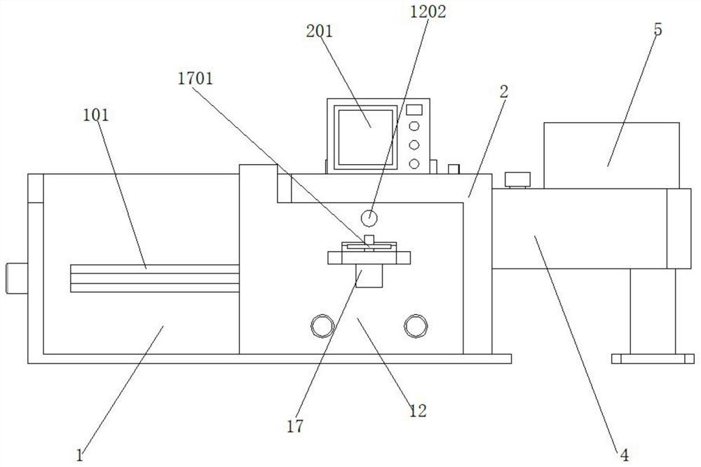
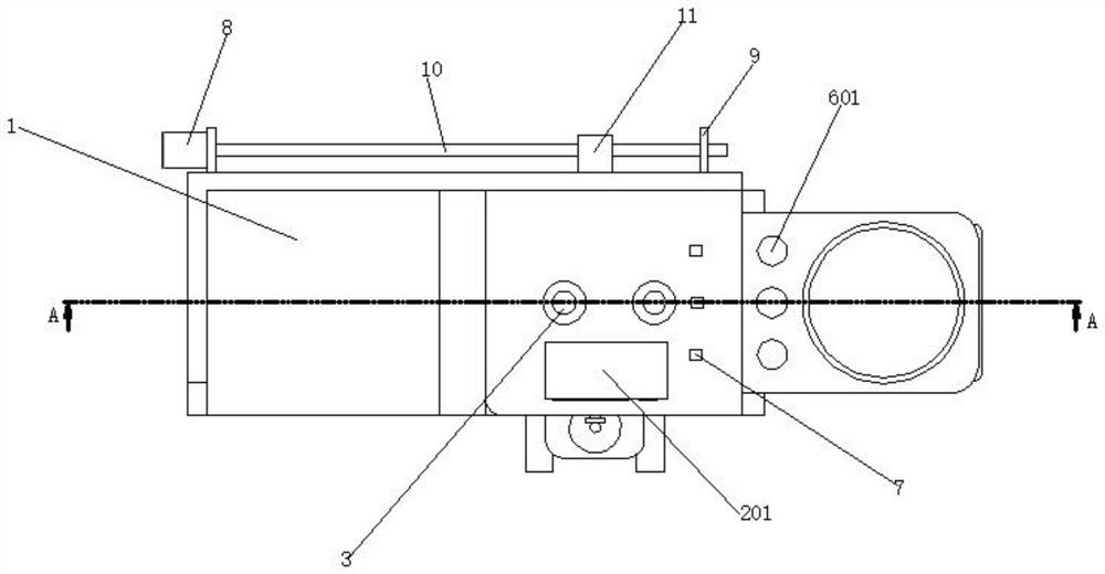
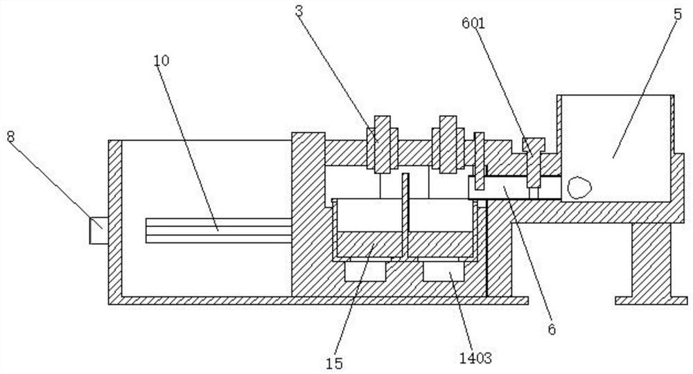
[0030] Such as figure 1 , figure 2 , image 3 , Figure 4 , Figure 5 , Figure 6 , Figure 7As shown, a impurity treatment apparatus having detecting and filtration of the NMP solvent, including the base 1, the cartridge 2, the visual detecting sensor 3, the supporting seat 4, placed bucket 5, the guide tube 6, the infrared liquid detector 7 The first step feed motor 8, the fixing plate 9, the screw 10, the adjustment block 11, the filter holder 12, the placement tank 13, the adjustment tub 14, the filter pad 15, the mounting plate 16, the second step, the motor 17, the The casing 2 is fixed to the right side of the base 1, and the card cover 2 is connected to the base 1, the visual detecting sensor 3 is fixed to the left and right sides of the interior of the cartridge 2, the visual detection The inductor 3 and the casing 2 are connected by a bolt, the support base 4 being fixed to the right side of the cartridge 2, and the support seat 4 and the cartridge 2 use a bolted connection, the placed bucket 5 is fixed to support. The upper end of the seat 4 inside, the placement tub 5 is integrally formed with the support seat 4, the number of the guide tube 7 is a plurality of pieces, the guide tube 6 is fixed to the left side of the support seat 4, The flow tube 6 is integrally formed with the support seat 4, and the flow tube 6 is welded to the placement tub 5, the infrared liquid detector 7 is fixed to the left side of the guide tube 6, the The infrared liquid detector 7 is connected to the guide tube 6, and the infrared liquid detector 7 and the cartridge 2 are connected by a bolt, the first step of the motor 8 fixed to the rear end of the base 1 On the side, the first step of the motor 8 is coupled to the base 1, the fixing plate 9 is fixed to the left and right sides of the rear end of the base 1, and the fixed plate 9 and the base 1 use bolt connection. The screw 10 is rotated inside the fixing plate 9, the rod 10 and the fixing plate 9 with a rotating connection, and the rod 10 is connected to the first stepped motor 8, the rod 10 is connected to the first step. The adjustment block 11 is arranged in the outer wall of the rod 10, the adjustment block 11 and the wire rod 10, using an internal and external thread, and the filter holder 12 is slidably in the front end of the base 1, the filter holder 12 and the base The seat 1 adopts a bolted connection, and the filter holder 12 is connected to the adjustment block 11, the placement tank 13 is located inside the filter seat 12, the placement tank 13 as a circular groove, the adjustment bucket 14 is placed inside the placed slot 13, the adjustment tub 14 and the placement tank 13 rotate, the filter pad 15 is placed on the left and right sides of the inside of the adjustment tub 14, the filter pad 15 and the adjustment bucket 14 employ activity Connecting, the mounting plate 16 is fixed to the upper side of the filter seat 12, the mounting plate 16 integrally formed with the filter seat 12, the second step, the motor 17, is fixed to the bottom of the mounting plate 16, which The second step of the motor 17 and the mounting plate 16 are bolted;
[0031] It should be noted that the impurity treatment apparatus for detecting and filtering the NMP solvent is provided;
[0032] A. Place the tub 5 can be stored for the unfiltered NMP solvent, and the NMP solvent is poured into the regulating tub 14 by means of the guide flow tube 6, and the impurity filtration purposes of the NMP solvent can be achieved by the effect of the filter pad 15. ;
[0033] B. The visual detection sensor 3 can perform visual detection inside the adjustment tub 14, which is convenient to determine the impurity capacity of the top surface of the filter pad 15, which is convenient for subsequent staff to clean up, and the infrared liquid detector 7 can be internal NMP in the guide pipe 6 The impurities in the solvent are analyzed, and therefore the number of flowers 6 is a plurality of pieces, but not only the shunt can be achieved, but also improve the fluid effect, but also the detection of the infrared liquid detector 7, convenient for the staff judgment analysis;
[0034] C. The first step of the motor 8 drives the rod 10 to rotate, and can drive the adjustment block 11 to the left and right slide on the base 1, slide to the left side of the filter holder 12, facilitate exposure to the placement tank 13 and the adjustment bucket 14. Convenient subsequent staff to change the filter pad 15 inside the adjustment barrel 14 to avoid long-term use of occlusion problems;
[0035] D, the second step of the motor 17 can drive the adjustment tub 14 rotation, and then facilitate the adjustment tub 14 to switch, by placing the filter pad 15 of different apertures 15 on the sides of the adjustment bucket 14, and then according to the infrared liquid The detection analysis of the detector 7 achieves the switching regulation of different aperture filtration;
[0036] The inner rear end of the base 1 is also provided with a guide hole 101, and the guide hole 101 is a rectangular via, and the guide hole 101 is slidable with the adjustment block 11;
[0037] It should be noted that the guide hole 101 can do not affect the left and right sliding of the adjustment block 11, and realize the avoidance of the adjustment block 11;
[0038] The front end of the card cover 2 is further provided with a control panel 201, the control panel 201 and the cartridge 2 employ a bolted connection, and the control panel 201 is respectively connected to the visual detection sensor 3, the infrared liquid detector 7 The first step feed motor 8 and the second step-in motor 17 are connected to the electrical signal line;
[0039] It should be noted that the control panel 201 can easily switch operation control of the visual detection sensor 3, the infrared liquid detector 7, the first step feeder 8, and the second step.
[0040] The tube 6 is further provided with a regulating valve 601 in the upper end, and the adjustment valve 601 is coupled to the guide tube 6, and the regulating valve 601 and the support seat 4 are bolted.
[0041] It should be noted that the regulating valve 601 can switch to the smooth and blocking state of the guide tube 6, which is conducive to the regulating flow;
[0042] The export tube 1201 is also provided with the export tube 1201 on both sides of the front end of the filter seat 12, and the export tube 1201 is welded to the filter seat 12, and a metal sensor 1202 is also secured to the upper side of the filter seat 12. The metal sensor 1202 is connected to the filter seat 12, and the metal sensor 1202 is connected to the second step-of-step motor 17;
[0043] It should be noted that the export tube 1201 can discharge the NMP solvent after filtration, and achieve the flow of the flow, the metal sensor 1202 can trigger the second step of the motor 17 to stop operation after detecting the separator 1401, and realizes the adjustment bucket 14. 180 ° rotation control;
[0044] A avoidance tank 1301 is also provided on the left and right sides of the inner lower end in the lower end, and the avoidance tank 1301 is a groove, and the avoidance tank 1301 is integrally formed with the export tube 1201;
[0045] It should be noted that the avoidance tank 1301 can make it easy to adjust the NMP solvent inside the tub 14 through the avoidance tank 1301 to the export tube 1201;
[0046] The inside of the adjustment tub 14 is further provided with a separator 1401, and the separator 1401 is welded to the adjustment tub 14, and the top portion of the adjustment bucket 14 is further provided with a driven gear ring 1402, the The driven gear ring 1402 is integrally formed with the adjustment tub 14, and there is a fluid hole 1403 on the left and right side of the inside of the adjustment tub 14, and the fluid hole 1403 is a circular via;
[0047] It should be noted that the separator 1401 can separate the adjustment tub 14, realize a separate filtering process on the left and right sides, the driven gear ring 1402 can be rotated with the active gear 1701 to rotate, and the fluid hole 1403 can facilitate adjustment bucket 14 The internal NMP solvent flows into the discovery groove 1301 below;
[0048] The second step of the motor 17 is further secured, and the active gear 1701 is coupled to the second step of the motor 17, and the active gear 1701 and the driven gear ring 1402. Turntable connection;
[0049] It should be noted that the active gear 1701 can rotate under the driving of the second step of the motor 17, followed by rotation of the driven gear ring 1402 to achieve the rotation of the adjustment tub 14.
[0050] The above is merely the preferred embodiment of the present invention, and it should be noted that several improvements and variations can be made without departing from the technical principles of the present invention, these improvements and variations can be made without departing from the technical principles of the present invention. It should also be considered as a scope of protection of the present invention.

PUM

no PUM

Description & Claims & Application Information

We can also present the details of the Description, Claims and Application information to help users get a comprehensive understanding of the technical details of the patent, such as background art, summary of invention, brief description of drawings, description of embodiments, and other original content. On the other hand, users can also determine the specific scope of protection of the technology through the list of claims; as well as understand the changes in the life cycle of the technology with the presentation of the patent timeline. Login to view more.
Why Eureka
Try Eureka