
Liquid flow valve structure and using method thereof

A flow valve and liquid technology, applied in the field of flow valves, can solve problems such as inability to dynamically adjust the flow valve in the pipeline system, lack of flow, internal impurity adsorption and treatment, cavity blockage, etc.

Inactive Publication Date: 2021-07-06
尹红富
View PDF0 Cites 0 Cited by
  • Summary
  • Abstract
  • Description
  • Claims
  • Application Information

AI Technical Summary

Problems solved by technology

[0006] The object of the present invention is to provide a liquid flow valve structure and its use method to solve the above-mentioned background technology. It is difficult for the flow valve body to block the flow of the incoming liquid. Liquid flow is dynamically adjusted. During use, the flow valve lacks a structure for absorbing and treating impurities inside the flow. Metal impurities inside the liquid and waste inside the pipeline will cause clogging of the cavity inside the flow valve body.

Method used


Image

  • Liquid flow valve structure and using method thereof
  • Liquid flow valve structure and using method thereof
  • Liquid flow valve structure and using method thereof

Examples


Embodiment Construction

[0028] The technical solutions in the embodiments of the present invention will be clearly and completely described below with reference to the accompanying drawings in the embodiments of the present invention. Obviously, the described embodiments are only a part of the embodiments of the present invention, but not all of the embodiments. Based on the embodiments of the present invention, all other embodiments obtained by those of ordinary skill in the art without creative efforts shall fall within the protection scope of the present invention.

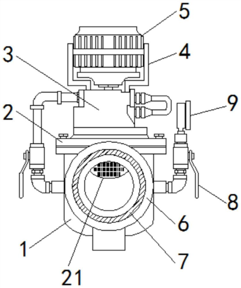
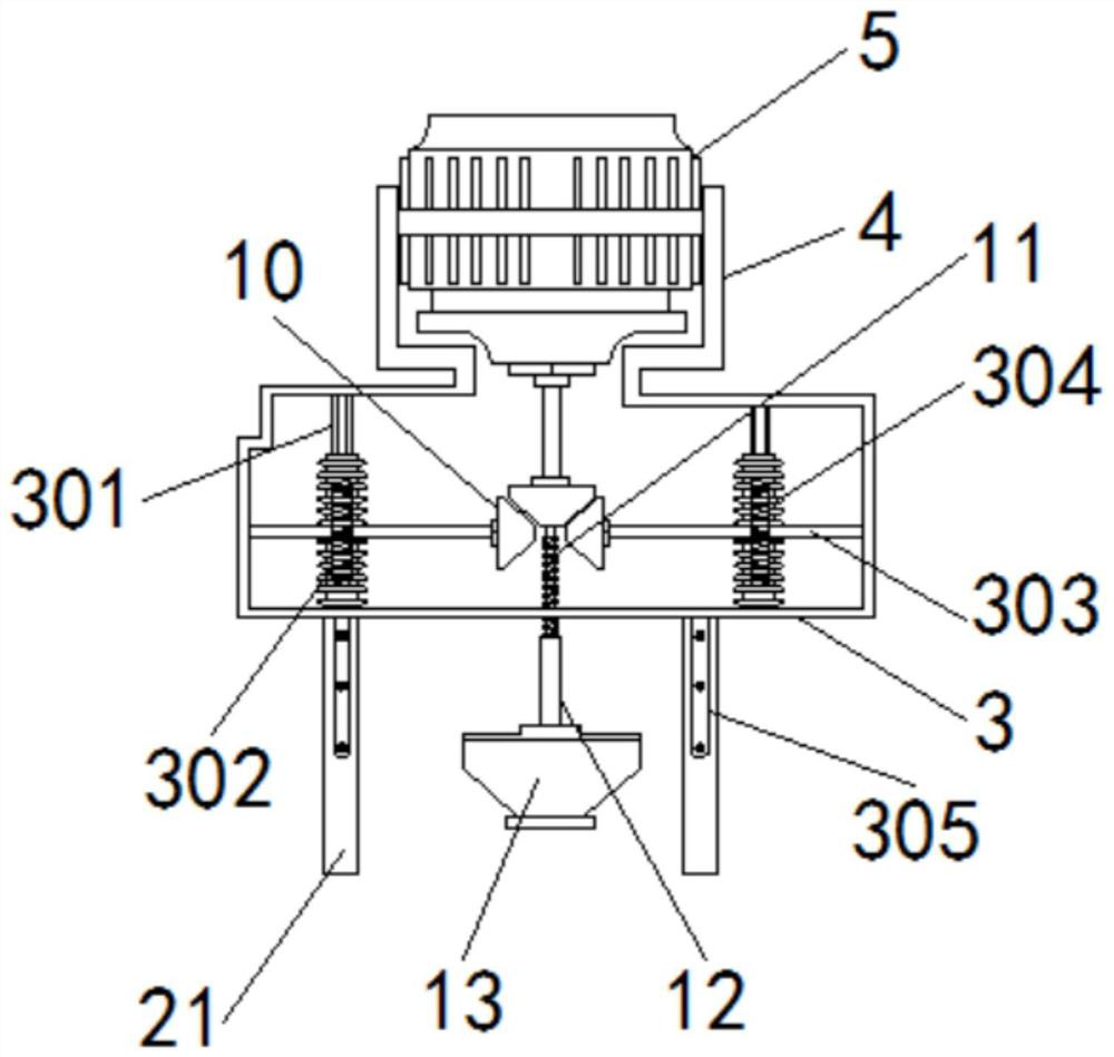
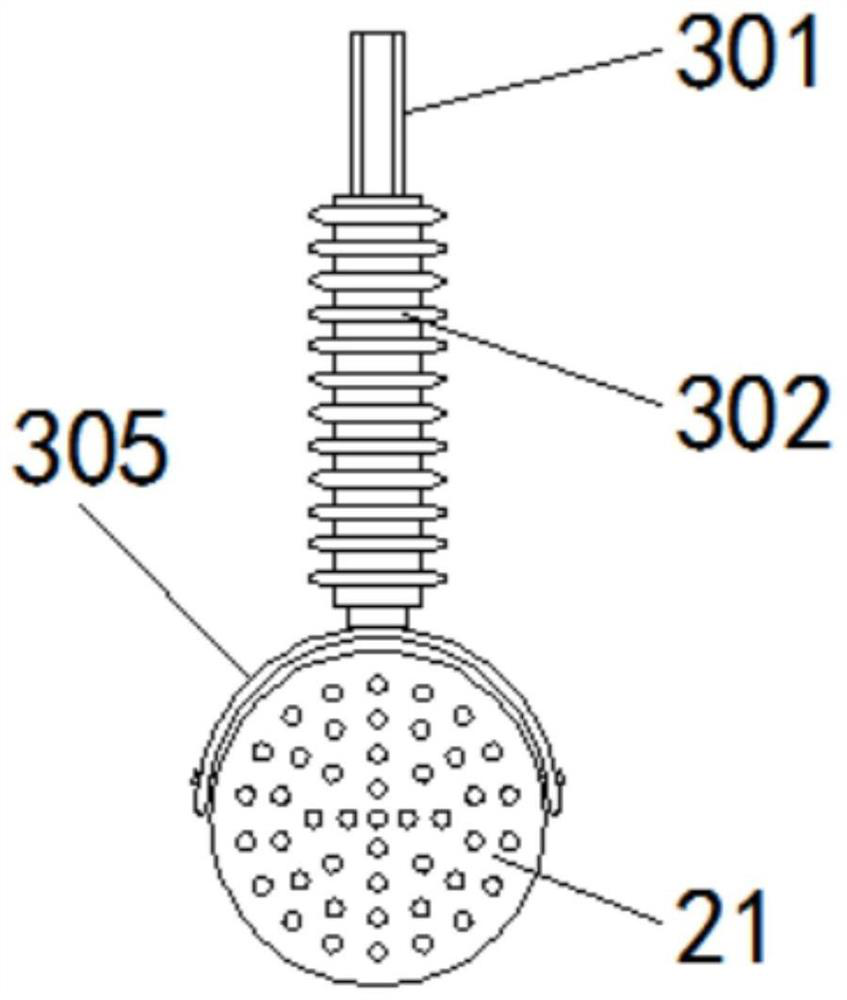
[0029] see Figure 1-7 , the present invention provides a technical solution: a liquid flow valve structure and its use method, including a flow valve body 1, a valve body cover 2, an equipment box 3, a first lift panel 4, a drive motor 5, an inlet Liquid pipeline 6, plastic ring gasket 7, valve handle 8, flow meter 9, bevel gear 10, ball screw 11, female threaded pipe 12, valve core 13, water inlet through hole 14, sealing gasket 15,...


PUM


Abstract

The invention discloses a liquid flow valve structure and a using method thereof. The liquid flow valve structure comprises a flow valve body, a liquid inlet pipeline, valve handles, a ball screw, an inner threaded pipe and a valve element; a valve body cover plate is fixed directly on the flow valve body through bolts, and an equipment box is fixedly welded directly on the valve body cover plate; and a first lifting panel is fixedly welded on the equipment box, a driving motor is fixedly installed on the outer side of the first lifting panel, the liquid inlet pipeline is fixedly welded to the outer side of the flow valve body, a plastic ring pad is fixedly bonded to the outer side of the liquid inlet pipeline, and a flow instrument is connected directly with one of the valve handles through a pipeline. According to the liquid flow valve structure and the using method thereof, bevel gears and limiting pieces are arranged, the bevel gears are used for driving worm wheels on the left side and the right side to rotate, and the worm wheels are used for driving a worm on one side to vertically ascend and descend; and according to the requirement for the flow velocity of fluid, the worm drives a flow blocking panel to vertically descend so as to control the drainage range of a water inlet through hole.

Description

technical field [0001] The invention relates to the technical field of flow valves, in particular to a structure of a liquid flow valve and a method of using the same. Background technique [0002] The flow valve is suitable for the pipeline system that needs flow control, especially for the flow control of non-corrosive liquid media such as heating and air conditioning. The flow valve can automatically eliminate the hydraulic imbalance caused by various factors in the water system and keep users The required flow rate is adjusted by the throttle area between the valve core and the valve body and the local resistance generated by it, so as to control the movement speed of the actuator; [0003] During the use of the liquid flow valve, the liquid is mainly blocked by the valve core. During the use process, for example, during the transportation of tap water, since there is no solid impurities in the tap water, the liquid flow valve can transport the liquid, and it will not ha...

Claims


Application Information

Patent Timeline
Patent Type & Authority Applications(China)
IPC IPC(8): F16K1/02F16K1/36F16K1/32F16K27/02F16K31/04F16K31/53F16K31/50B03C1/02
CPCB03C1/02F16K1/02F16K1/32F16K1/36F16K27/02F16K31/04F16K31/50F16K31/53
Inventor 尹红富
Owner 尹红富
Learn More