Digital optical processing machine

A digital optical processing and optical machine technology, applied in optics, instruments, projection devices, etc., can solve problems such as poor optical path accuracy, unfavorable module heat dissipation, and structural deformation of the whole machine

Active Publication Date: 2021-07-06
深圳市安华光电技术股份有限公司
View PDF7 Cites 0 Cited by
  • Summary
  • Abstract
  • Description
  • Claims
  • Application Information

AI Technical Summary

Problems solved by technology

Although this method can improve the installation accuracy to a certain extent, with the long-term operation of the optical machine, on the one hand, it is easy to deform the structure of the whole machine due to the heat of the environment and the light source, and the interaction between different optical modules, especially At the junction where the propagation direction of the optical path changes, it is easy to cause errors in the optical path propagation, resulting in poor optical path accuracy and reduced energy utilization; on the other hand, since each module is installed in the same h

Method used


Image

  • Digital optical processing machine
  • Digital optical processing machine
  • Digital optical processing machine

Examples


Embodiment Construction

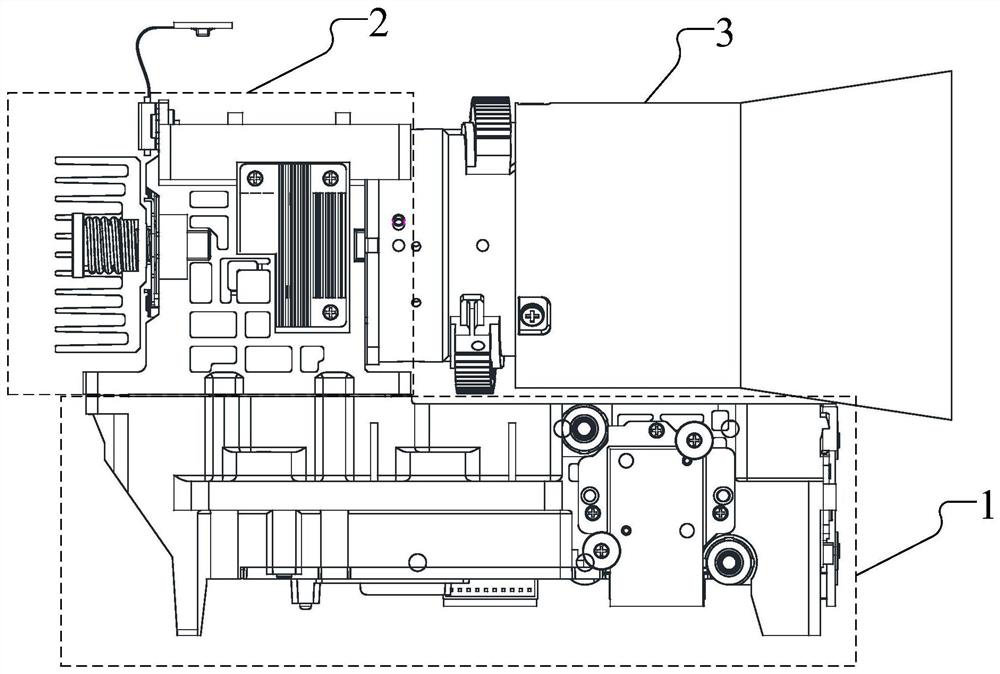
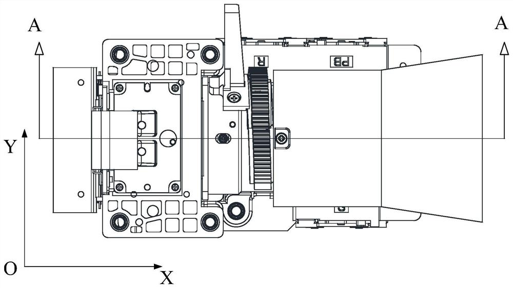
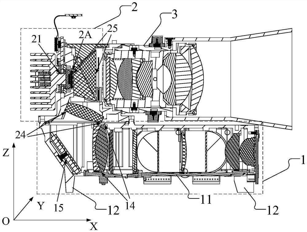
[0030] In order to improve heat dissipation, reduce the interaction between different optical modules, and save floor space, this embodiment discloses a digital light processing optical machine, please refer to figure 1 , figure 2 and image 3 ,in, figure 1 It is a schematic structural diagram of an opto-mechanical main view disclosed in this embodiment, figure 2 It is a schematic structural diagram of an opto-mechanical top view disclosed in this embodiment, image 3 disclosed for this example figure 2 Schematic diagram of the A-A cross-sectional structure.

[0031] Please refer to figure 1 , figure 2 and image 3, the digital light processing optical machine disclosed in this embodiment includes: a first optical path module 1, an optical modulation module 2, and a second optical path module 3, which are respectively provided with a first lens group, an optical modulation device, and a second lens group, wherein: the first An optical path provides incident light t...


PUM


Abstract

The invention discloses a digital light processing machine, which is characterized in that a light modulation module and a second light path module are stacked at the upper end of a first light path module, so that in a three-dimensional coordinate system taking a connecting point of the light modulation module and the first light path module as an origin of coordinates, the light path propagation direction reaches a projection lens in the negative direction of an X axis, the positive direction of a Z axis and the positive direction of the X axis in sequence; the projection area on the XOZ plane is larger than the projection area of the digital light processing machine on the XOY plane; supporting legs extending in the negative direction of the Z axis are arranged on the side wall of the first light path module and used for supporting the first light path module, so that an interval space exists between the lower cover plate and the end face of the workbench; and the interval space accommodates a plurality of wiring terminals connected with an optical device in the first optical path module, and provides a heat conduction channel for the plurality of heat conduction holes. The overall heat dissipation effect of the digital optical processing machine is improved, and the overall occupied area of the digital optical processing machine is also reduced.

Description

technical field [0001] The invention relates to the technical field of DLP projection, in particular to a DLP micro-projector, an optical machine thereof, and a digital light processing optical machine. Background technique [0002] Micro-projection technology is a new type of modern projection display technology. With its miniaturization and portability, it gradually penetrates into people's daily life, and has gradually become an important development trend of projection display. The digital light processing (Digital Light Processing, DLP) projection display method has the characteristics of high brightness, high contrast, and high resolution. It is combined with a new LED light source to realize a miniaturized portable micro-projection, which meets people's desire for portable and free projection display. demand. [0003] The projection imaging quality of a DLP projector is closely related to the optical path and the fixing method of optical components. DLP projectors o...

Claims


Application Information

Patent Timeline
IPC IPC(8): G03B21/14G03B21/16G03B21/20
CPCG03B21/142G03B21/16G03B21/206G03B21/2066
Inventor 程炎高怡玮杨浩孙峰
Owner 深圳市安华光电技术股份有限公司
Why Eureka
Try Eureka