A joint-adjustable precision parallel external fixator

An external fixator and adjustable technology, applied in the direction of external fixator, fixer, etc., can solve the problems of external fixation work space with a single connecting rod, insufficient swing angle range of universal joint movement, small work space of external fixator, etc. Achieve the effect of avoiding shaking and length changes, promoting bone growth, and reducing interference

Active Publication Date: 2022-06-07
BEIJING UNIV OF TECH
View PDF10 Cites 0 Cited by
  • Summary
  • Abstract
  • Description
  • Claims
  • Application Information

AI Technical Summary

Problems solved by technology

[0004] Publication No. WO2017131309Al and Publication No. US20100312243Al respectively provide a parallel Taylor-type external fixator with ball bearing joint and fisheye ball joint, but they do not solve the problem that the swing angle range of the ball joint is small, resulting in a small working space for the external fixator , a singular position type appears; the patent CN02229946 is based on the Irizarov annular external fixator, which improves the structure of some parts and improves its practicability, but does not change its adjustable degree of freedom
[0005] Existing external fixators have a single structure and generally use 6 connecting rods, resulting in interference between the connecting rods, which affects the entire external fixation workspace, and the insufficient range of motion swing angles of universal joints or ball joints often leads to problems such as jamming ; The length-adjustable connecting rods of the existing external fixators all rely on the lead screw and the lead screw nut to adjust the length, which cannot achieve self-locking and cause relative shaking and rotation between the lead screw and nut, causing errors in adjustment; directly hand-tighten the screw The lever nut will produce a large adjustment range, resulting in excessive or insufficient change in the length of the connecting rod, causing unnecessary pain to the patient

Method used


Image

  • A joint-adjustable precision parallel external fixator
  • A joint-adjustable precision parallel external fixator
  • A joint-adjustable precision parallel external fixator

Examples


Embodiment Construction

[0032] The present invention is described in detail below in conjunction with the various embodiments shown in the accompanying drawings, but it should be noted that these embodiments are not restrictions on the present invention, and those of ordinary skill in the art according to these embodiments make functions, methods, or structural equivalent transformations or substitutions, are within the scope of protection of the present invention.

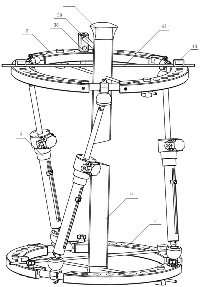
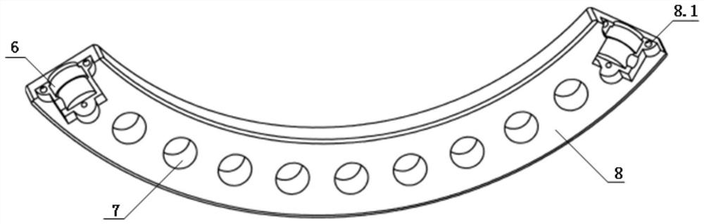
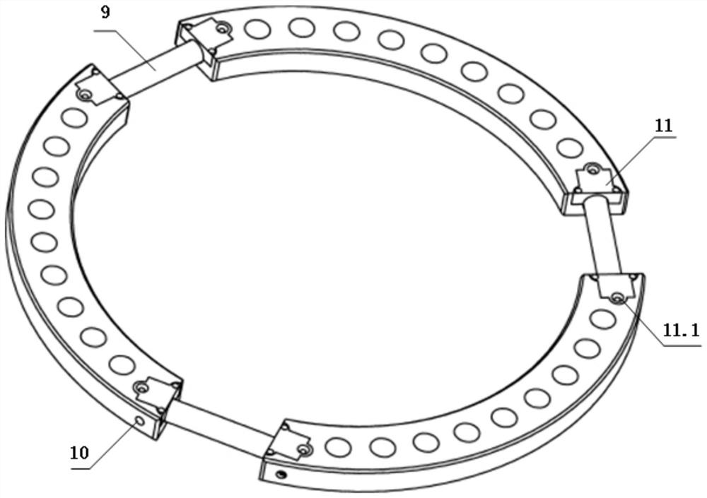
[0033] ginseng Figures 1 through 15 as shown, Figure 1 is a joint adjustable joint adjustable joint of the present invention in parallel external fixator overall assembly view; Figure 2 it is a proximal fan-shaped ring with a center angle of 100°; Figure 3 is a holistic view of the proximal fixing ring of the present invention; Figure 4 is a top view of the proximal fixing ring; Figure 5 is a cross-sectional view of the proximal fixing ring and a local enlarged view of its bearing grooves; Figure 6 is the overall diagram of the connecting ro...


PUM


Abstract

The invention provides a joint-adjustable precision parallel external fixator. The external fixator has six degrees of freedom, including a proximal fixing ring, a distal fixing ring, three connecting rods, a ball joint, a Kirschner wire, and a needle clamp. . The length of the connecting rod is adjusted by the worm and worm, and a rotating drive pair composed of a pair of bevel gears is set at the distal fixed ring to adjust the angle of the ball joint relative to the distal fixed ring, thereby changing the pose of the distal fixed ring and completing the three-dimensional deformity correction. Each ball joint in the present invention can realize independent adjustment and locking, so as to make up for the problem that the range of swing angle of the ball joint is small. The three connecting rods use worm gears to adjust their lengths, and the rotation of the worm knob is converted into a small change in the length of the connecting rods, so as to avoid drastic changes in the length of the connecting rods caused by human errors and other factors, and avoid unnecessary damage.

Description

Technical field [0001] The present invention relates to a kind of orthopedic surgery-specific parallel external fixator, specifically to a kind of tibial deformity correction parallel external fixator for fracture reduction, bone deformity correction. Background [0002] In recent years, with the continuous progress of science and technology, the rapid development of the transportation industry and the influence of factors such as environmental pollution, the number of patients with limb fractures and bone deformities has shown an increasing trend every year. An increasing number of orthopedic traumas and congenital limb deformities are affecting people's normal lives. As a traditional bone deformity correction device, the external fixator is slowly pulled according to the "tension-stress law" to stimulate tissue regeneration and reconstruction, and is widely used to treat fractures, bone deformities, limb lengthening and other problems. [0003] The parallel external fixator has...

Claims


Application Information

Patent Timeline
Patent Type & Authority Patents(China)
IPC IPC(8): A61B17/62
CPCA61B17/62A61B2017/603
Inventor 李剑锋刘吉祥刘顺启李国通杜祖淦
Owner BEIJING UNIV OF TECH
Why Eureka
Try Eureka